Copyright © 2013,2014 Joseph Mack, released under GPL v3
07 Sep 2014
Abstract
After restoration this scope has acceptable optics and is a nice addition to my observing equipment.
As I got further into the difficult parts of the restoration, I found the design and manufacturing is somewhere between negligent and incompetent. This was originally an expensive scope and high quality would be expected. Some things would have cost only pennies to do properly. In other places (the secondary mount) absurd amounts of money must have been spent, to no good effect. There was no QA or QC. While initially I was enthusiastic to fix whatever I found as I worked my way through, I hadn't expected so much to be wrong and to find so little pride in workmanship at Tasco. I could have produced a version of this scope, fit for use, in the same budget.
Still a working scope, even if badly designed and manufactured, is better than no scope. I spent 4 months of my spare time on this, at an hour or two a day.
Table of Contents
- 1. Introduction
- 2. Cleaning the Front Plate, the Secondary and the Corrector Lens
- 3. Optical cleaning kit
- 4. OTA, Mounting Rings, rotationally locking the OTA
- 5. Focuser
- 6. Cleaning the Primary
- 7. Alignment
- 8. Conversion from 0.965" to 1.25" eyepieces
- 9. Pointers and Finders
- 10. First Light: it works!
- 11. A Scope for the US
- 12. Disassembly of Secondary Mount: Tools
- 12.1. pin-type face spanner
- 12.2. gloves
- 12.3. hex key, grub screws and cap screws
- 13. Disassembly of Secondary Mount
- 13.1. Secondary disassembled, nomenclature
- 13.2. Secondary Stalk, 3-axis tilt
- 13.3. Secondary Stalk: Disassembly
- 13.4. Secondary Stalk: gratuitously complicated
- 13.5. Secondary Stalk: Longitudinal Adjustment
- 13.6. Ungluing and Regluing secondary mirror
- 13.7. Corrector lens assembly and inside locking ring
- 14. Alignment/Collimation of Secondary
- 15. Vinyl plastic shower caps considered harmful to optics
- 16. Optical bits
- 17. Polaris Scope
- 18. Simplified drift polar alignment without cross-hair eyepiece
- 19. Tripod
- 20. The role of telescope reviewers in magazines
- 21. Moon Photos
- 22. Miscellaneous
- 22.1. Suppliers
The history of this line of scope is unclear to me. It was a Vixen line sold in the 1980's under the Tasco name, a brand associated in the US with department store telescopes.
Table 1. Completed Tasco 8V
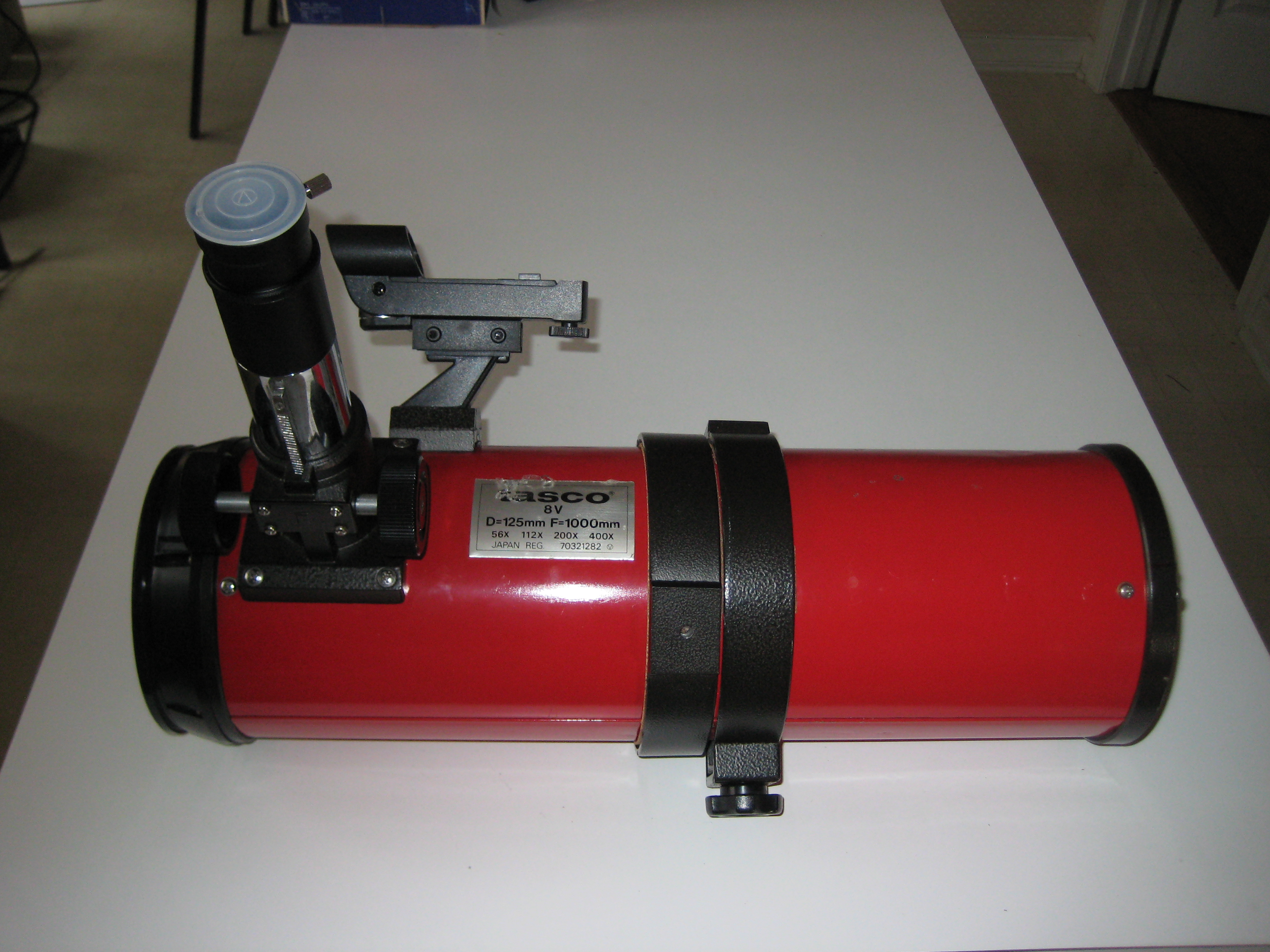
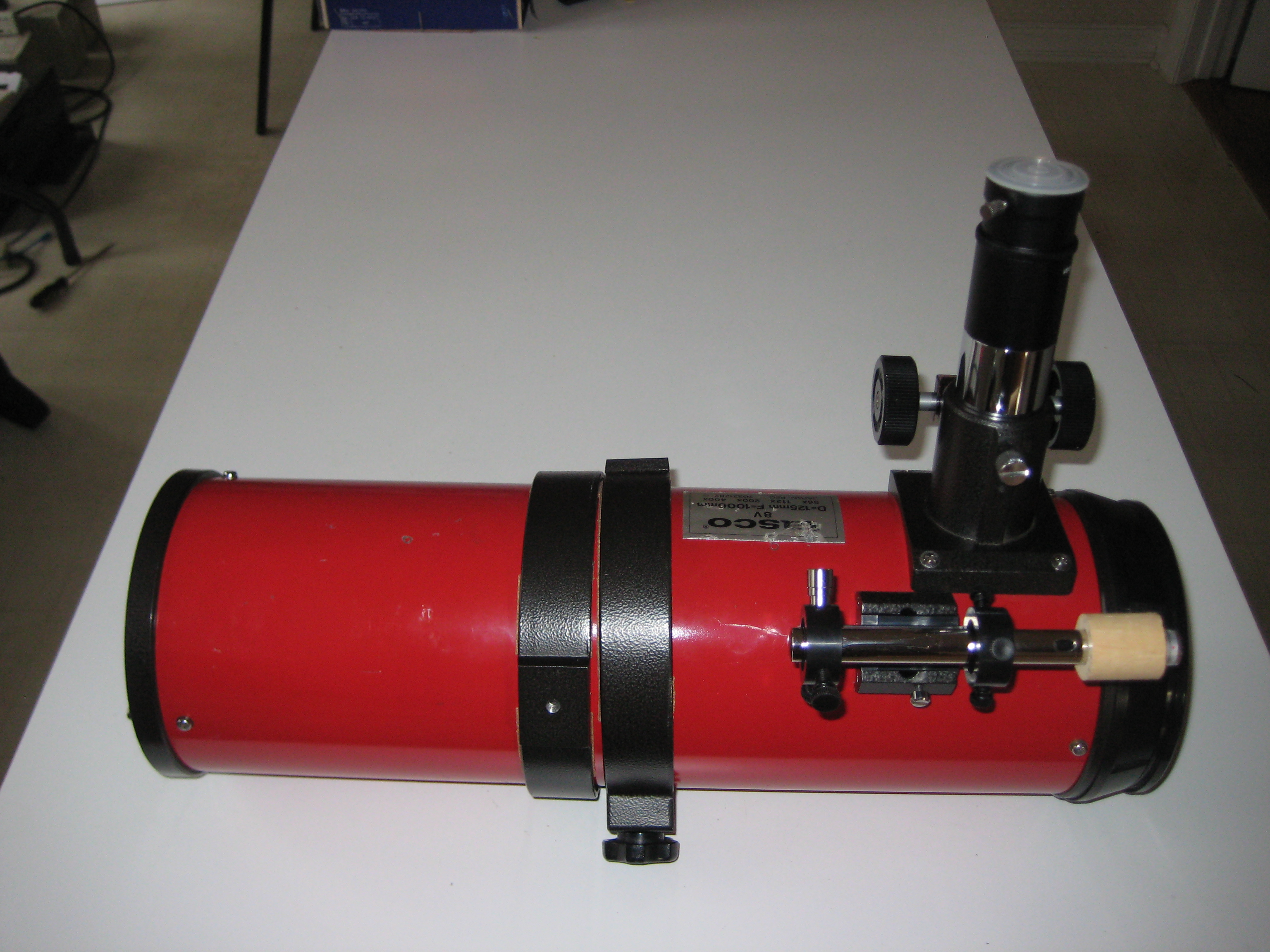
My first job was to figure out the best performance I was likely to get from this scope, so that I would know how much effort to put into it. The scope came with a 0.965" focuser and eyepieces, which (I've been told) were standard inside Japan at the time, but are only found on department store scopes in the US. The small aperture eyepieces restricted the scope to relatively high magnifications. This coupled with the relatively small scope aperture, 125mm, limited the observer to bright compact objects. All scopes back in those days were expensive, and this was no exception (on the internet, I've seen US$1690 as the original MSRP, with all accessories and eyepieces). Presumably it was pitched to amateur observers expecting good optics. This particular scope came with what at first sight appeared to be a solidly built, top of the line, equatorial mount and tripod. (I later changed my mind about the tripod; see tripod I haven't dismantled the equatorial head, so I can't say anything authoritative about it. The equatorial head has backlash, but probably no worse than expected in this price range.)
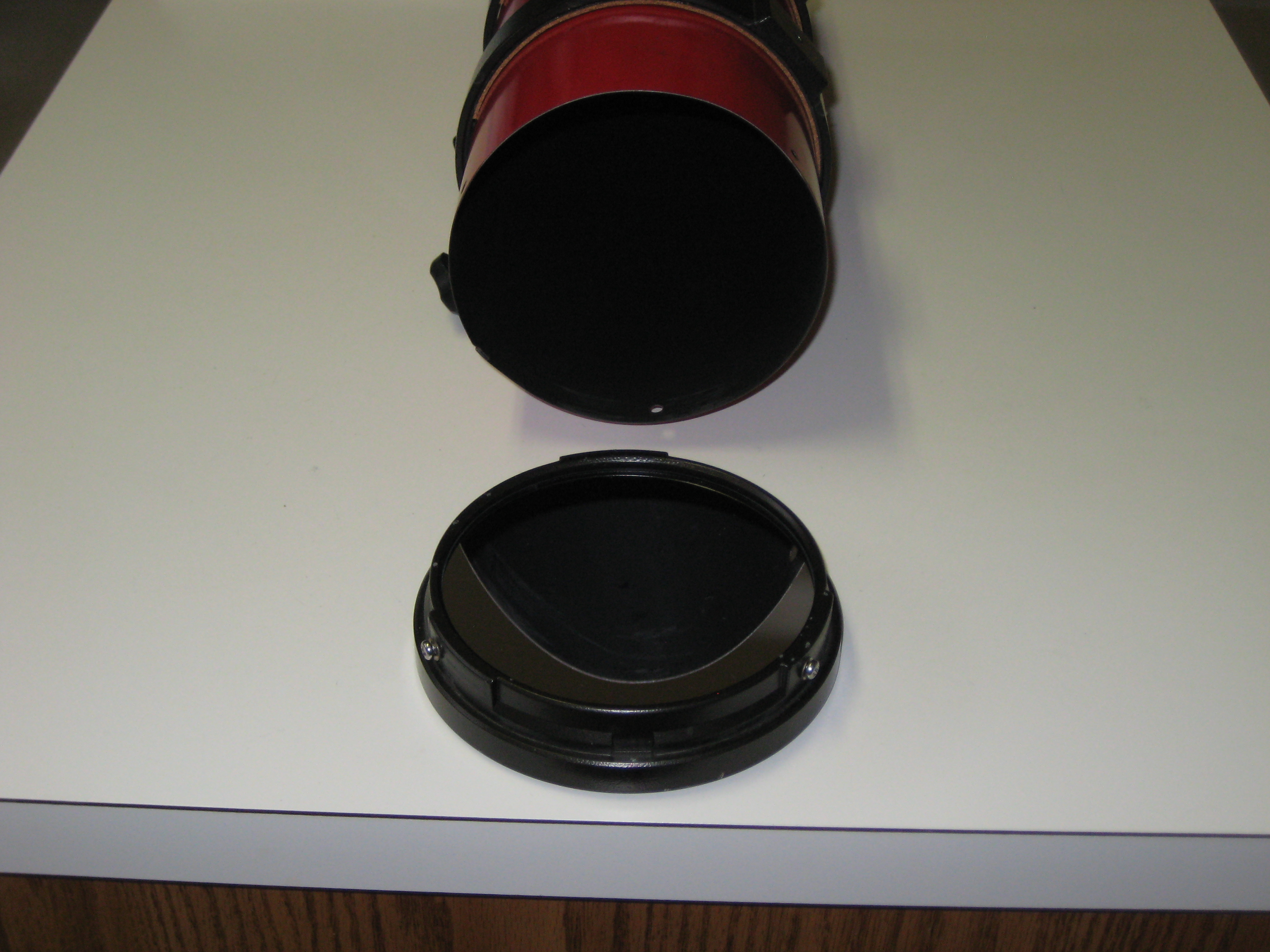
The optical design is Jones Bird, giving a short newtonian style telescope. The primary is spherical 125mm with a measured f/3.3 [1]. There is a small negative focal length corrector lens just before the secondary, giving f/8 at the eyepiece [2] . The secondary is mounted on an uncoated glass plate, rather than a spider, keeping the insides relatively clean. (The plate has no optical function; it's just the support for the secondary.) There is a cap for the front of the scope, keeping the outside of the plate clean.
For general information on the Jones Bird design:
-
From Rutten and van Venrooij
[3]
.
Section 13.4: Focal Correctors; Jones, Bird and Brixner.
"The ray tracing results, presented in fig 13.9, reveal that it is difficult to achieve a good performance with these systems. The reason for this is that three abberations (spherical, coma and color) must be corrected simultaneously with a simple doublet. The axial color correction of the the third system, the Jones-Bird, appears to be good, but the system exhibits both astigmatism and field curvature. "
Section 16.7.6 Results of Ray Tracing
In fig 16.24, the abberations of the Plossl eyepiece and the Jones-Bird objective when combined in a telescope, partially cancell.
- A 16" f/5 Jones Bird, at the Astronomical Society of Eastern Missouri [4] . This scope represents a substantial investment in time and would not have been undertaken without some confidence in the Jones Bird design. The construction page includes references to Jones, who worked on the spherical abberations, and to Bird who worked on the chromatic abberations [5] .
- Manly's book [6] refers to Jones' article in Sky and Telescope, Sept 1957, p548.
- the abberations inherent in the J-B design by Vladimir Sacek [7] .
The telescope had been originally owned by Max, the father of a friend Pete. Max had introduced me to analemmas. Here's my adventures with analemmas, including a few photos of Max [8] . When the family started the planning to move Max into a retirement home, I let Pete know that, if there was no other interest from the family in the scope, I'd love to have it. I grew up in Australia, and now live in the US. Every 2yrs or so, I return to Sydney for a month of R&R, bushwalking in the Blue Mts with my friends, including Pete and I usually visit Max. This scope would give me a scope in Sydney and had sentimental value attached to Max. Max moved into the retirement home after I returned to the US, and on my next trip to Australia, the scope was waiting for me, at the house of my bushwalking friend Chris, my alternate home in Sydney.
My initial problem was that the front plate had a film, both inside and out, on about half the area. I couldn't imagine where it came from. No-one in Max's house smoked. When not in use, the scope sat covered on it's tripod in the house. I couldn't imagine why only half the plate was covered in film, and I couldn't imagine how anything got on the inside. To get what I saw, they would have had to remove the cover on the scope, the cover on the focuser and the front cover and let off an insecticide bomb in the house. Max was a lot smarter than that. I couldn't think of anything that made sense (at least for a while, see vinyl, maybe Max used a plastic cover).
How to disassemble it to clean it? I expect scopes with front plates to be sealed, requiring special tools and impossible to disassemble, without an almighty and irreversible sproing. Even if I got it apart, with the limited number of adjustments available in this design, I didn't know how I was going to collimate it on reassembly. If the plate was fogged, presumably the primary was in similar condition.
Google searches revealed that people had problems with the Jones Bird design, which had been used in low end scopes, with little attention to mechanical detail, and a poor corrector lens, giving the design a bad reputation. The postings on the scope were confusing. Many people called it a Schmidt-Catadioptric (it isn't) because of the front plate. Others "experts" said it was difficult to collimate. After fixing up the scope, it's now clear which postings to read, but back then, I had no clue. (I ignored them all and figured everything out from scratch.) There didn't seem like many were still using this scope; it didn't look like many were sold, and presumably those that once existed were no longer in use (if they still existed). There was no-one with a properly aligned and cleaned example of this scope stating clearly an unequivocally (with evidence) that it worked well.
The scope and I were in Sydney, while the people I knew who understood scopes were in USA. I didn't want to spend my vacation without tools, a clean area, and people to ask questions, trying to restore this scope with no assurance of success, when I'd come to Sydney to bushwalk. I could see myself leaving a partially restored scope, that I couldn't reassemble, in Sydney and returning to the US, to spend the next 2yrs wondering what I'd do with the scope on my return.
I started a series of e-mail exchanges with Jim, an amateur astronomer friend back in the US, who has been building scopes and grinding mirrors almost since he was a kid. After talking to Jim, as a test run, not requiring any disassembly, I bought lens cleaner and cloth from a camera store and found I could remove much of the film on the outside of the plate. This showed that the film was grime, rather than chemical etching and that the optics were likely recoverable. Jim has seen it all and done it all and wasn't at all worried by the symptoms. He told me to bring the scope back to USA, wrapped protectively in towels in my luggage, and we'd fix it back here. (I left the mount and tripod in Sydney.)
It wasn't till I reached the end of the restoration, that I found I had a good performing scope. However back then, sitting in Australia, with an unusable scope of unknown potential, it seemed that carting the scope back to the US, only to return with scope of marginal quality 2yrs later, could turn out to be folly. Still I had a scope in poor shape. Anything I could do with it would make it better. I didn't have a scope in Australia and even a marginal scope would be better than none.
On my return to USA, I took the scope around to Jim's on weekends over about a 2 month period. He provided most of the ideas, and did most of the initial work, while I acted as his assistant, watched and learned. I'd go home and work until I hit a brick wall and would go back to Jim's.
After the intial steps of restoration (cleaning plate and primary, adjusting the primary), I decided I liked the scope and wanted one for the US and one for Australia. I bought a second scope from Milt on Cloudy Nights [9]. It would appear that the design changed with time. The two scopes are different colours, one is bright red, one is dark red. One has 6 screws to adjust the primary (3 locking, 3 adjusting), the other has only 3 screws (no locking screws). The scopes had different problems. Max's scope had obvious alignment problems, which I didn't know how to fix, as I thought the secondary mount was set at the factory. Still it was quite usable. Milt's scope was nicely aligned.
Where the scopes are different, you will see references to the first (Max's) or second (Milt's) scope.
Before starting disassembly, I wanted to know that I could at least restore the scope to its current level of alignment. An artificial star test showed reasonable collimation along with astigmatism. As my knowledge of the scope increased, I realised that this wasn't a valid test. There was no centre dot on the primary. so we couldn't attempt to collimate it. At this stage, no matter what we found, I was committed to tearing down the scope, so I didn't record the results of our tests and just started in on it.
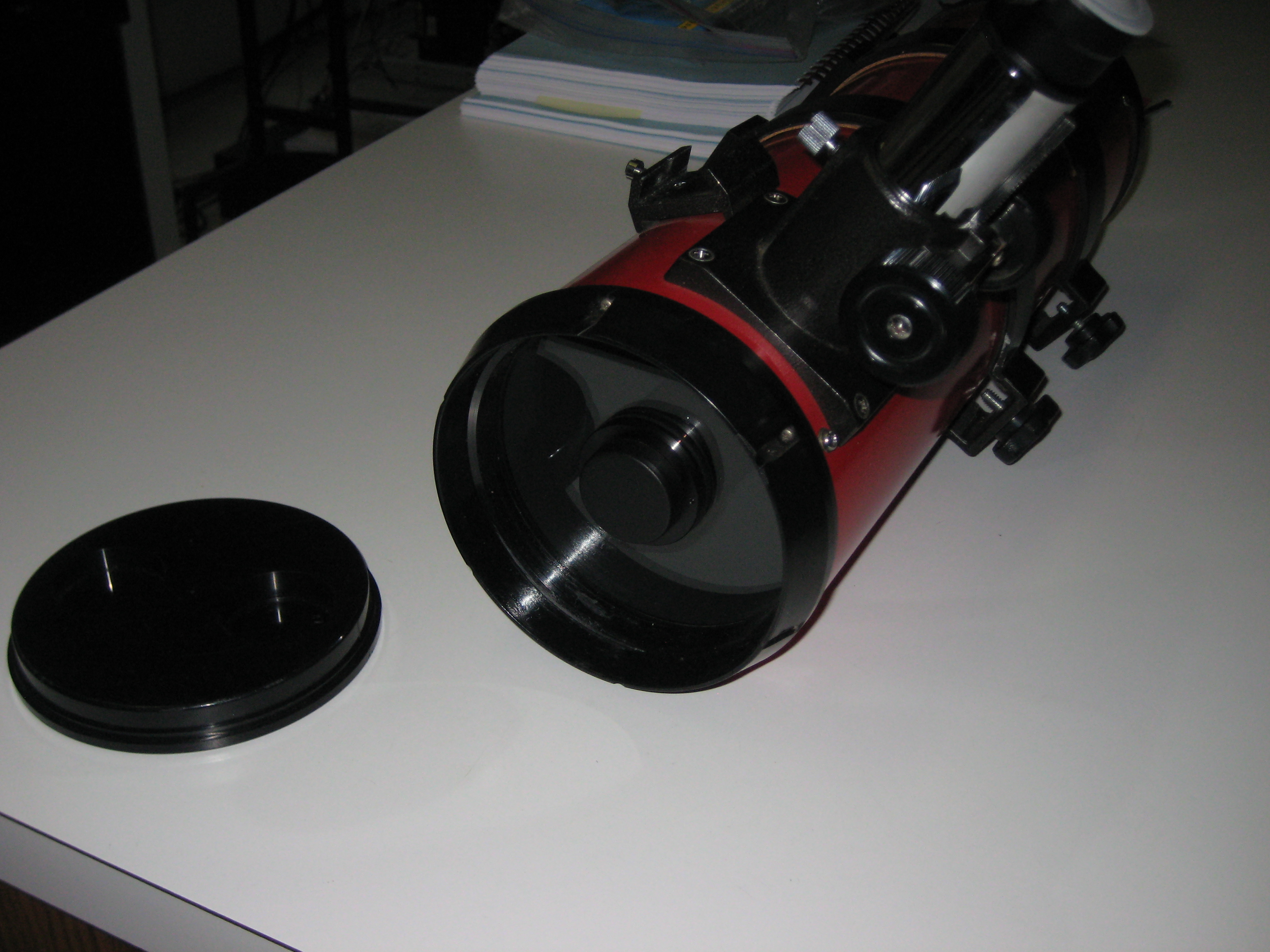
To my great relief, the front plate came off simply with 3 screws.
The OTA is not circular; there is a pucker at the seam. When the scope is not in the mounting rings, this pucker makes it difficult to insert the screws for the plate and the primary; the holes in the OTA don't align with the screw holes in the plate and the primary. You start with a screw in one hole and then push the OTA to depucker it for the next two screws. When the scope is in the rings and using Milt's ring locking mechanism (see Milts blocks), the OTA becomes circular again and there's no problem aligning holes and threads.
 | Note |
|---|---|
My 2nd Tasco 8V (from Milt) had slots, instead of holes, for the plate mounting screws. This allows you to insert all screws without having to depucker the OTA. After the screws are in, the slots allow a small amount of rotational adjustment to the secondary, without having to adjust the grub screws on the secondary mount. I'm not sure whether slots are a good idea; it means there's no hope of putting the plate back into the scope in the original orientation. But even on my scope with holes, rather than slots, the scope never came back spot on and had to be realigned on reassembly. So I don't know if the slots are a good or a bad idea. | |
The plate is attached with Phillips screws (M3x0.5) each with two flat washers. I replaced the outer flat washer with a split ring washer.
| Note |
|---|---|
In my 2nd Tasco 8V (from Milt), the plate is attached with slotted screws (also M3x0.5). You shouldn't have slotted screws anywhere that a screwdriver slippage will cause problems. I replaced the slotted screws with Phillips head screws. | |
| Note |
|---|---|
The scope has two different threads for the structural elements; the focuser and Synta shoe are M4x0.7, the plate and primary are M3x0.5. there is no reason to have two different threads. There is plenty of metal on the plate and the primary mirror cell. It would have been simpler for these threads to all be M4x0.7. simpler | |
As disassembly progressed (below), I found that the plate and later the primary came apart and reassembled simply and easily. This was not a Schmidt-catadioptric design, with complicated mechanics. The scope was a tin can OTA (optical tube assembly), with a front plate screwed in one end and the primary screwed in the other end. (However the secondary was a nightmare, see secondary disassembly tools and secondary disassembly.)
A marker pen (down the seam of the OTA, and onto ring holding the front plate), was used to assure reassembly in the original of 3 symmetric orientations. This proved unnecessary; there's only one orientation that points the secondary to the focuser, but we didn't know that at the time.
I've watched Jim clean eyepieces before and never had the courage to attempt it myself. Jim brought out his cleaning kit, with multiple magic cleaning solvents, cotton pads (from the pharmacy, for removing makeup - there are abrasive versions for scouring your face, don't use them), and cans of air blaster. The labels on these cans go to great pains to tell you that they don't contain chlorofluorocarbons (whose phaseout started in 1994 [10]), but they are strangely silent on what they do contain. They very likely contain greenhouse gas fluorocarbons (e.g. tetrafluoroethane, R134a with a global warming potential of 1430 times that of CO2 [11] and with a residence time in the atmosphere of 1000's yrs (these gases can no longer be sold in most 1st world countries).
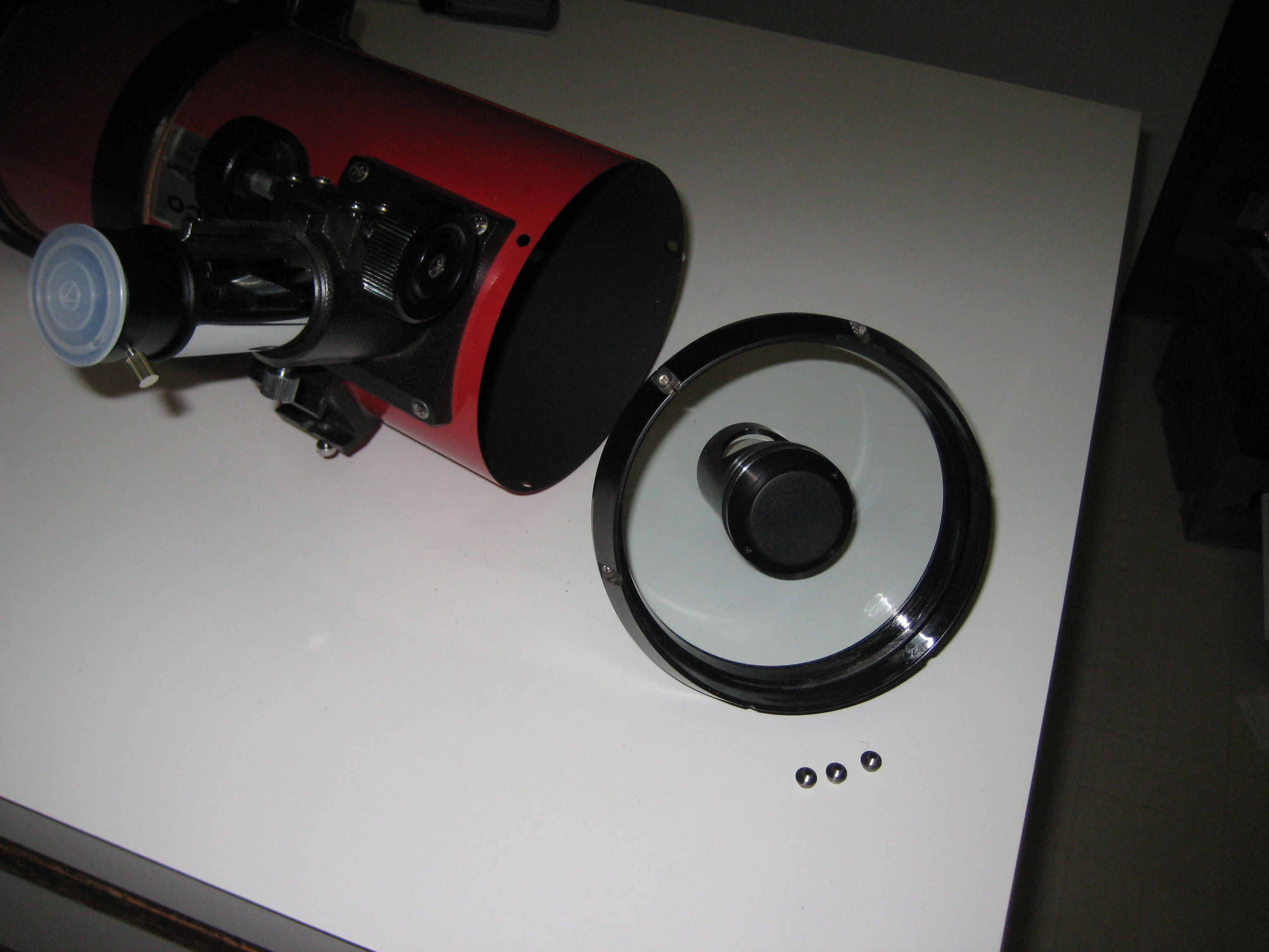
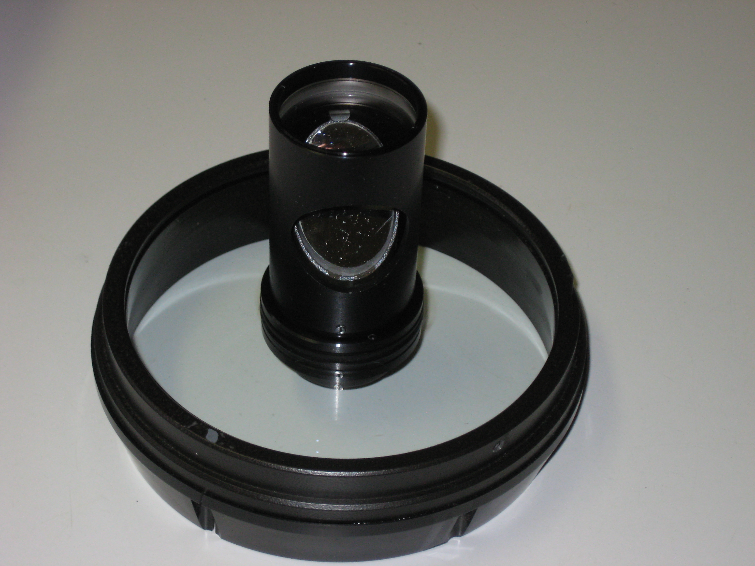
The front plate, the secondary, the corrector and the ring which attaches to the OTA, come off together. In the photo, the corrector is above the secondary. (This photo was taken after restoration; note the secondary already has dust.)
At this stage we weren't going to mess with any more than was needed and the order of the day was to see if the plate was recoverable, so we didn't further break down the plate. If you do this, you have to re-align the secondary and corrector (see the photos by Steve_M_M [12] ). I didn't find these photos or posting until I'd finished the restoration. I later found that the normal secondary adjustments are available, but are inside and require further disassembly (see secondary disassembly tools and secondary disassembly). If you go in there, be careful; you're working in proximity to the plate, rather than in mid-air like you are with a Newtonian. I didn't know about or change any of these adjustments. As it turns out the alignment was good enough for preliminary viewing and I didn't tackle the secondary till later.
Jim wet the cotton pads with one solution after another and then wiped the plate dry, till there was no more film on the either side of the plate. The plate cleaned up. This was good news. Jim cleaned up the secondary and the corrector, which was also a mess. The major problem I saw in Australia was handled.
| Note |
|---|---|
| Jim starts with acetone, something that I was a bit wary of because of its interaction with plastic. Sure enough we got into trouble with plastic. I'll use alcohol instead (in the US isopropanol, in Australia metholated spirits). This is good for removing fingerprints. The isopropanol I used (or the cotton wipes I was using) left a residue on the mirror. This was washed off with distilled water. | |
I took the scope home to figure out how to align it. This is simple enough mathematically when you have all the adjustments, but with a scope like this, when I didn't know that there were adjustments, I expected you'd have your work cut out for you if anything was missaligned.
Here's the front plate after restoration

Over the time of the restoration, I removed and replaced the plate many times and did many alignments. All of these operations require care not to touch or scratch the plate. Initially I accepted the plate as a given; it was there and I had to work with or around it. However after a couple of months of this, it occured to me that much of my problems was caused by the plate and the secondary mount. I can see no benefit of having the plate; a 3 vane spider would do just as well. With a spider, there's no problem with touching air or having sharp tools in air. If you need to work near a piece of glass, as for the Tasco 8V, you have to be able to do it with plastic tools. The plate is an albatross. Tasco didn't even single coat it. In a manufacturing run, coating it would have added maybe $1 to a $1690 scope.
It was time for my own optical cleaning kit. I couldn't go to Jim every time I needed something cleaned (which admittedly was only every couple of years, and was a good excuse to get together with Jim). There was lots of advice on the internet on cleaning optics. The problem was that I couldn't tell what would happen if you combined advice from two different people.
Company Seven has a self consistent all encompassing webpage [13] on cleaning.
I set off to but the whole kit from my local camera/photography store. My first shock was that it didn't exist anymore. It was there only a couple of years ago. I remember buying a $5 case for the P&S camera I'd just got from Craig's list. How could it have gone out of business already? :-) Not only that, going on-line, I found that there was only one camera store left in the area. There must have been half a dozen not too long ago. From what I can see, they were all bought up by Wolf camera, who then closed them down. Well the one remaining store had been around for years; he'd have everything I needed. I found it a museum of every camera manufacturer and every model. Back in the old days, he used to have ROR by the gallon, but not anymore. I guess everyone throws away their cameras before the lenses get dirty. I thought about the loss of expertise that once was available in these stores. Waving his arms in the direction of cameras whose names I well knew, he lamented their extinct US camera manufacturers. I exchanged nostalgia with him, remembering what this equipment meant to me when I was a kid. I was the only customer in 30mins. The parking lot outside was empty save for my car. There was no room on the shelves for merchandise to sell. He wasn't selling anything that people buy now. I couldn't see how this guy could pay his rent. I went home and bought it all on-line.
Following the advice of Company Seven, I bought
- Zeiss Lens Cleaner
- Residual Oil Cleaner (ROR)
- Tiffen Lens Cleaner (FKA Kodak Lens Cleaner, Kodak EK 176 7136). Company Seven recommends the Kodak Lens cleaner, but it's not available anymore. The Tiffen lens cleaner has the same Kodak numbers (at least on the website; the bottle, when you get it, just says "Tiffen Lens Cleaner" with no Kodak number).
On-hand I already had alcohol, cotton pads and distilled water (not filtered water, which still has the minerals in it).
Advice from Al Nagler (well TeleVue) [14] showed that he doesn't get too stressed about cleaning fluids.
From Jim
In truth, many cleaning options are available. I think even Windex is (or was) suggested by Televue at one time. The bottom line is that whatever works without harming coatings it fair game. The main thing is to take care to remove any abrasive materials from the optical surface before proceeding with liquids and the Q-Tip. Then, use a light touch, a bright light and proceed with care.
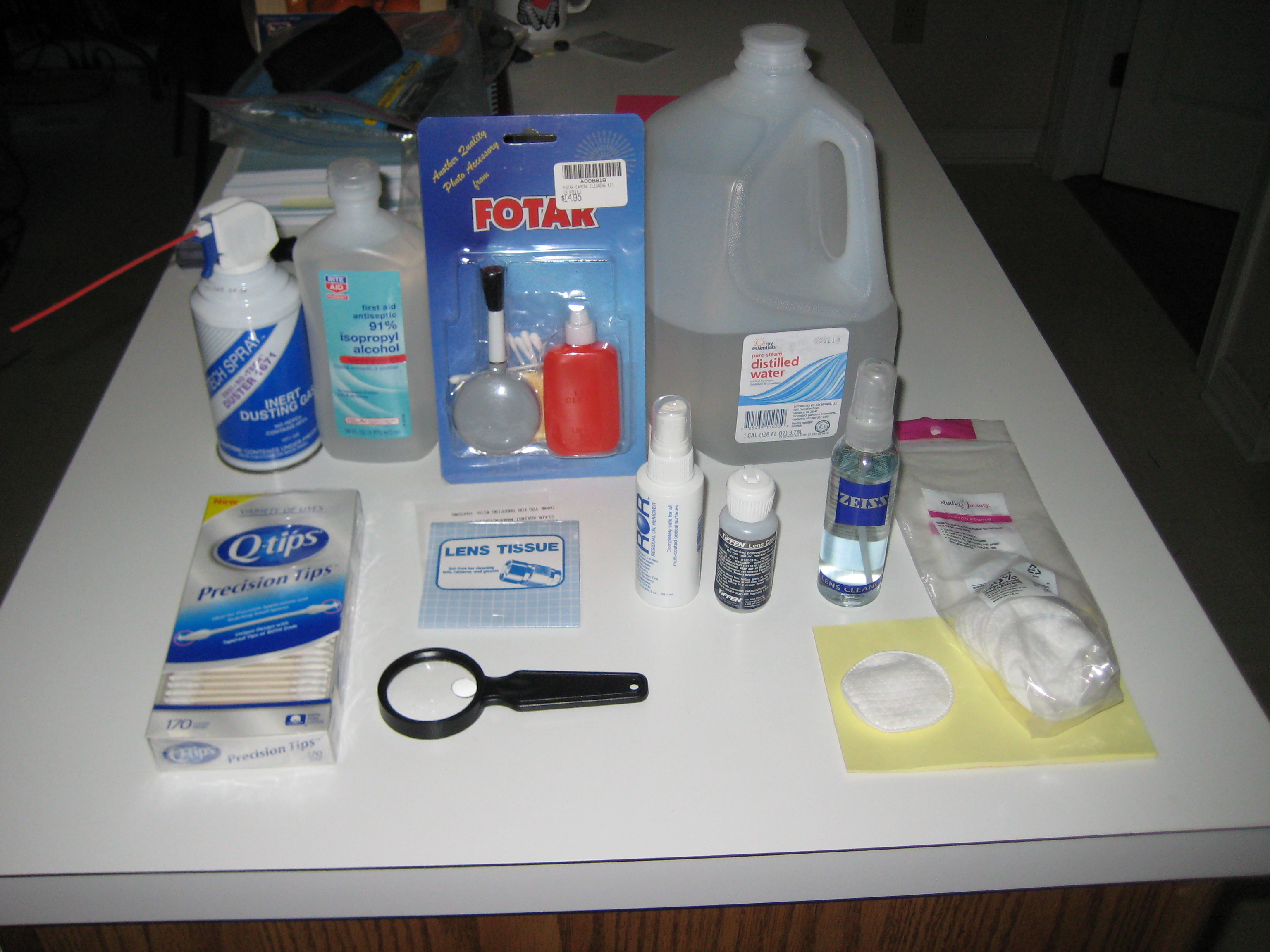
Cleaning kit
- back row (l to r): greehouse gas, isopropanol, lens cleaning kit from camera store in Australia (camel hair brush, cleaning fluid, lens tissue), distilled water.
- front row (l to r): Q tips (cotton on a stick), magnifying glass, ROR, Tiffen, Zeiss cleaning fluids, (on yellow postits) single cotton pad and bag of cotton pads
Later I bought acetone (from the paint section in the hardware store, where it's sold as paint thinnner). Acetone isn't great stuff. It dissolves most plastic (you can pour it into a glass cup, but not a plastic cup). You can pick things out of acetone with your hands (it just removes the grease from your skin, leaving it whiter looking), but don't do it any more than necessary. Don't use gloves with it - they will dissolve. For extended periods it will cloud the eyes (permanently, but you would have to be standing in a tank of acetone for a while for this to happen). It will smell inside the house. Pads soaked in acetone should be placed in a bowl of water, or thrown in the sink where you can then run water over them, then squeezed out (by hand is OK), then put in the garbage. The bowl of dilute acetone/water can be flushed down the sink.
The magnifying glass was part of an experiment that didn't work. Usually you look for dirt or film on an eyepiece by holding it in various angles in the sun. You can see dirt on the top of the top element, but that's it. You can't see the outside of the bottom element (which admittedly is usually cleaner), as it's hidden deep inside the eyepiece. Then one time at Jim's place he showed me one of the new 600 lumen flashlight/torches. This one was a Streamlight ProTac HL. These have a narrow (0.5cm) white beam and when you shine them through an eyepiece, you can see the dirt on the outside of the top element and the outside of the bottom element (when viewed from below), but you can also see the dirt on the inside of the top element. You don't have to move the eyepiece through various angles. The dirt/film is easy to see. One reason it beats the sun, other than being brighter than the sun, is that the rest of the eyepiece is not illuminated, so the bright specs of dirt are easier to see against the background of the dark interior of the eyepiece.
Except that these 600 lumen devices are $60, I would forget about the sun. I'm going to wait for the price to go down.
A long focal length magnifying glass converges the light slowly, and in the sun, creates a shadow around the converging beam. One difference is that the sun has a lot of heat, whereas the flashlight/torch is creating white light from a phosphor. I tried the magnifying glass on a eyepiece in the sun, keeping the eyepiece moving so there'd be no local hot spots. It worked a little bit like the high power flashlight/torch, expect the dirt wasn't as easy to see and I had to keep moving the eyepiece, rather than getting a good look at what was going on. As well I got some strong return flashes from inside the eyepiece which kept blinding me.
The problem with the magnifying glass is that the emerging light is converging. You want a column of light that doesn't con/diverge much, to illuminate the glass in the eyepieces, without illuminating the eyepiece body, The Tasco has a 6*30 finder scope which I've replaced with a red dot finder. I tried using the finderscope with the objective pointed at the sun and the other end at the eyepiece. This is more difficult than just pointing the flashlight into the eyepiece. It works better than the magnifying glass, but not as well as the high intensity narrow beam flashlight.
I'm going to keep using the sun to inspect eyepieces for a while.
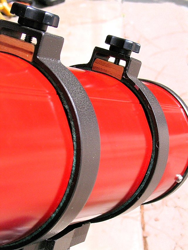
The OTA is sheet metal. The mounting rings have screws with knobs to stop the OTA rotating. You expect the screws to suddenly tighten as a band tangentially restrains the OTA. Instead the screws bight radially directly into the sheet metal OTA, rather than onto some relatively large or thick plate or band. As you continue to tighten the screws, the sheet metal gives way without any obvious increase in tension. At night in the dark, you even can't see what's happening. Each tightening then leaves a crater in the OTA. People with inherited or used Tasco 8V's, comment on the state of the OTA. My OTA looked like a can that's been beaten with a hammer, with paint removed where a screw has been tightened. Apparently this design feature is a part of several Tasco scopes.
Before doing any alignment, I needed the OTA to be in its final geometric configuration. This meant getting the dings out, which might change the shape or orientation of the optics at the ends. (In retrospect removing the dings probably made no difference to the optics, since alignment was within range of the adjustments, but removing the dings did make the OTA look nicer.)
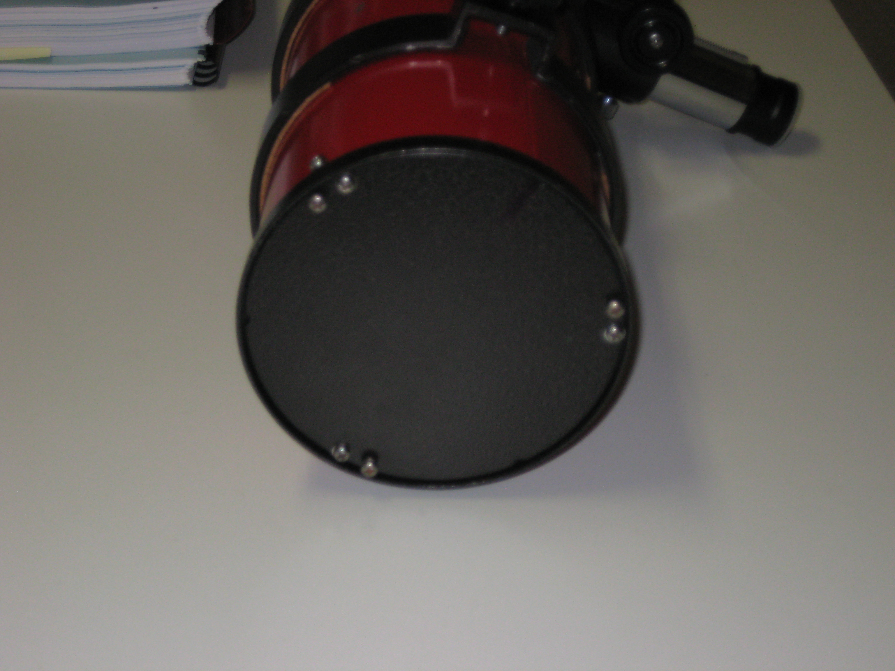
The photo above shows the cell holder from the outside. It is two pieces of metal. The inner part, the mirror holder, has 3 pairs of screws. One screw of each pair screws into the outer ring, which itself screws into the OTA with 3 screws. I first removed both pieces together, by removing the 3 screws holding the outer ring to the OTA (again marking the orientation of the outer ring and the mirror holder). I then removed the mounting rings for the equatorial mount, which slid off the OTA. I didn't remove the focuser or shoe; there were no dings in this region.
The primary surface was OK to a cursory inspection and I decided initially not to mess with it.
I beat out the dings from the inside using a brass hammer and a block of wood. The face of the hammer was slightly curved, approximately matching the curvature of the OTA. (A flat hammer may not have worked so well. Presumably a soft faced ball peen hammer would have been OK, but I didn't have one.) The brass was probably not necessary. It was the smallest hammer I had and the small size of the head was needed, to get inside the OTA. To see the bumps inside the black OTA, the OTA needed to be illuminated from the other end, to cast shadows. Both a regular indoor light and outdoor light, through a window on a cloudy day, worked well. I'd put the hammer on the bump, then raise the hammer about 1cm and give the bump a tap. Usually first or second tap was enough.
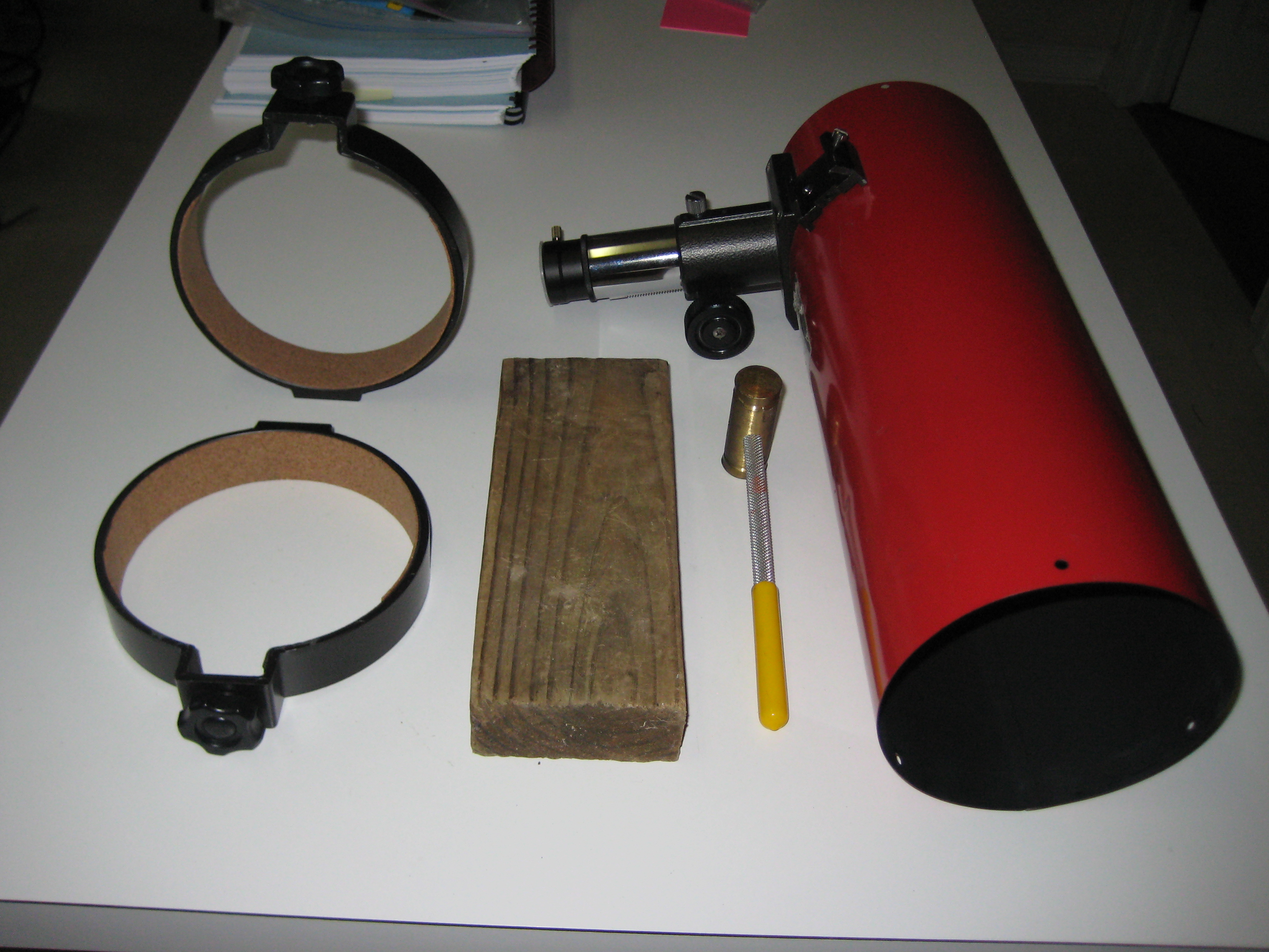
The photo shows the two mounting rings for the equatorial mount, after being lined with cork. The far ring is vertical, the near ring is flat on the table. Next is the block of wood, the brass hammer and the OTA.
The sides of the OTA were now flat (well flatter). I left the circular paint scars from the ends of the screws. There was no way I could paint to match the nice enamelled finish on the OTA. I decided that the scars added a touch of well travelled experience to the scope.
Inspection of the mounting rings and the screws showed no obvious way to fix the problem to alternately allow rotation of the OTA, then to lock it down. First I tried lining the rings with cork. It didn't work. Here's my cork method [15] .
Later I got a better fix from Milt Hays Jr., who I found through Cloudy Nights (he sold me my 2nd Tasco 8V), and who sent me this photo. Rather than having the screw push directly on the OTA, the screw pushes wooden blocks, and the larger area of the wooden blocks pushes on the OTA. It works perfectly. (I glued fender washers to the top of the blocks, so the screw pushes onto the fender washer and not the wood.)
There are two sets of knobs on the mounting rings. One set of knobs stops the OTA rotating (and inflicts the damage on the OTA described elsewere here). The screws on the other set of knobs clamp onto the equatorial mount. I had missmatched sets of screws. Presumably Max had lost the originals and picked up non-matching replacements with the right thread. I wanted a matched set. The scope comes from Japan, is metric (the label on the OTA has focal length and aperture in metric), the screws on the OTA are metric (M4x0.70, M3x0.5), the screws on the tripod are metric (M8x1.25, M5x0.8), so the screws on the rings are going to be metric, right? The nearest I could get was M6x1.25 but these didn't fit. Wrong. All four of these screws are 1/4"-20. Mars Climate Orbiter anyone [16] ? (I can't believe how long it took to figure this out. It never occured to me in a million years. I didn't even pull out my Imperial taps and dies to measure them against.)
So off to get some 1/4"-20 knobs. My hardware store doesn't have any knobs. (My told me people are asking for them all the time. Well, why don't you sell them then?)
I found knobs at Lee Valley Tools [17] .
These nuts (M4x0.7) are inside, are not captive and don't have washers. They have survived 30yrs held with paint and luck, but some were loose. I don't like hardware on the inside of the OTA that can escape and crash into the optics. To remove the focuser, you first have to remove the plate, so you can hold the focuser nuts on the inside of the OTA as you unscrew the focuser. It would be nice to be able to remove the focuser without first removing the plate. This would require captive nuts and would be a bit of bother. I decided I wouldn't be removing the focuser a whole lot. Instead I replaced the inside nuts (both shoe and focuser) with aero/nylocks.
The Synta shoe on the scope is slightly trapezoidal (the current batch of Synta shoe hardware has parallel sides) and narrower than current Synta feet (the feet wouldn't fit) (maybe the new ones are metric :-( ). In my first attempt to fix the problem, I widened the shoe with a file. My 2nd Tasco 8V had the same problem. I replaced both shoes with current wider Synta shoes, which have a large gap between the shoe and the foot. The head on the screws holding down the shoe were countersunk oval. The oval head allowed the original finderscope shoe to fit, but not the foot on the red dot finder or the green laser holder. I replaced the screws on the shoe with countersunk flat.
While trying to align the scope on an artificial star in my living room one day, the image of the artificial star, instead of coming to a point, had spikes coming out radially from the point. Jim diagnosed it over the phone as a reflection inside the tube. Sure enough, the chromed draw tube was projecting into the body of the scope. Either arrange the geometry such that the draw tube is outside the OTA at focus, or only look at stars at night.
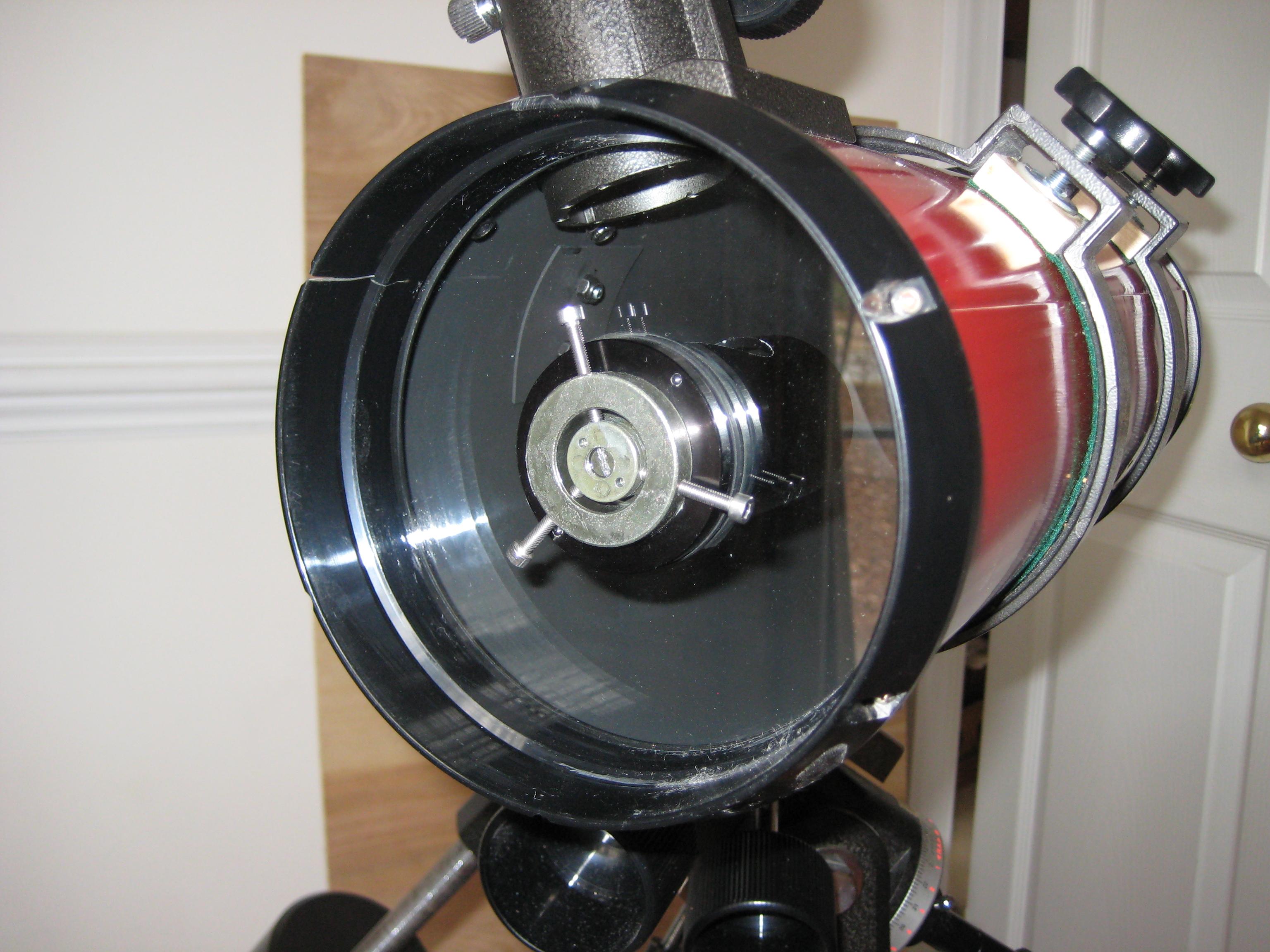
Although it's not initially obvious, the primary is between in two piece of metal.
- The mirror holder: when looking at the back of the scope this is the plate of almost the whole diameter of the OTA. It has 3 pairs of screws (3 adjusting and 3 locking) around the circumference.
- The mounting ring: this attaches to the OTA via screws. The mirror holder attaches to the ring via the 3 adjusting screws.
Although I doubt if it matters, I used marker pen to mark along the seam of the OTA, through the mounting ring and onto the mirror holder, to be able to restore both pieces, to their original of 3 rotationally symmetric positions.
The screws to the OTA release both pieces together.
While the primary looked OK inside the house, holding it at an angle in the bright sun, showed film on some of the surface. I separated the mirror holder from the outer ring, by unscrewing the screw of each pair that was holding them together. I then put the unit on the table mirror side up, and lifted the ring off the mirror holder.

I blew the dust off the primary with the greenhouse gas blaster. I wet the pads in turn with the various cleaning solutions, and gently wiped the mirror with them, rolling the pad upwards as I went, so that any dirt particles would be lifted off the mirror. After one pass across the mirror face, I discarded the pad, on the assumption that it had abrasive particles caught in it. I then dried the mirror by gently wiping it with dry pads, again rolling up the pad and discarding it after a single pass. No matter what I did, I wound up with horrible streaks on the mirror, presumably cleaning chemical residue. I found I could remove the residue by rinsing the mirror with distilled water. Drying the mirror with the pads left lint all over the mirror. The simplest drying method, was to shake off excess water and then blow off remaining drops of water (which were sticking to dirty spots on the mirror), with the greenhouse gas blaster.
This effected only a minor clean up of the mirror. To really do the job, I had to spray the mirror with a cleaning fluid, soak pads with the same fluid, and put pads on the mirror covering all the surface. I left the pads on the mirror for about 30mins for each solution, then rinsing with distilled water, and then drying with greenhouse gases. It took 2 rounds of each of the 3 cleaning fluids to get a clean mirror. There was an ellipse about 1"x0.5" of what may be mirror metal exfoliating that I could never get rid of, and which I could only see at a particular angle in the sun. I decided to accept it.
Unlike a cardboard sonotube, this metal OTA doesn't flex appreciably on changing elevation, nor does it change size and shape when dew descends from above. The alignment should survive many car trips. I expect alignment should stay in place for a long time.
In the initial stage of restoration, alignment took most of the elapsed time and much head scratching. I didn't know the specs of a showroom new scope, or any idea of the expected performance of one in good condition in the hands of an amateur. With the usual adjustments to the secondary and focuser fixed into the hardware, and no adjustment of the corrector available, I had a limited number of parameters to adjust.
My initial check of the scope, before I started disassemby, showed that the scope was near enough to collimated, but had astigmatism. Was it supposed to have astigmatism, I wondered. Was the astigmatism due to a tilted corrector that I wouldn't be able to fix?
These were new to me. I used the Hubble Artificial Star [18] . This device isn't particularly well made. As well, after inserting batteries, you have to iteratively align the LEDs inside with the holes on the outside, to get any light out. The mask is separate from the device, and can get lost, when it could easily be an integral part of the device.
However the device provides satisfactory artificial stars. Now to see stars, you no longer have to wait for a clear night, go outside to fumble and drop expensive hardware, in the dark and freezing cold. Instead you can do it in your well lit living room, at a comfortable temperature, anytime, day or night. You can scratch your head and think about things, without having to pull everything down and bring it back inside. Amateur astronomy has come a long way.
Being in the living room, the artificial star is close (about 15' in my case) rather than at infinity, so you have to raise up the eyepiece to focus on the artificial star. I bought 2 extender tubes 2" long. This put the eyepiece as high off the OTA as the OTA is long. I assume the close distance of the target adds spherical abberation to the image. (Since the equatorial mount for my scope is in Australia, I'm using my Dobs mount to rest this scope.)
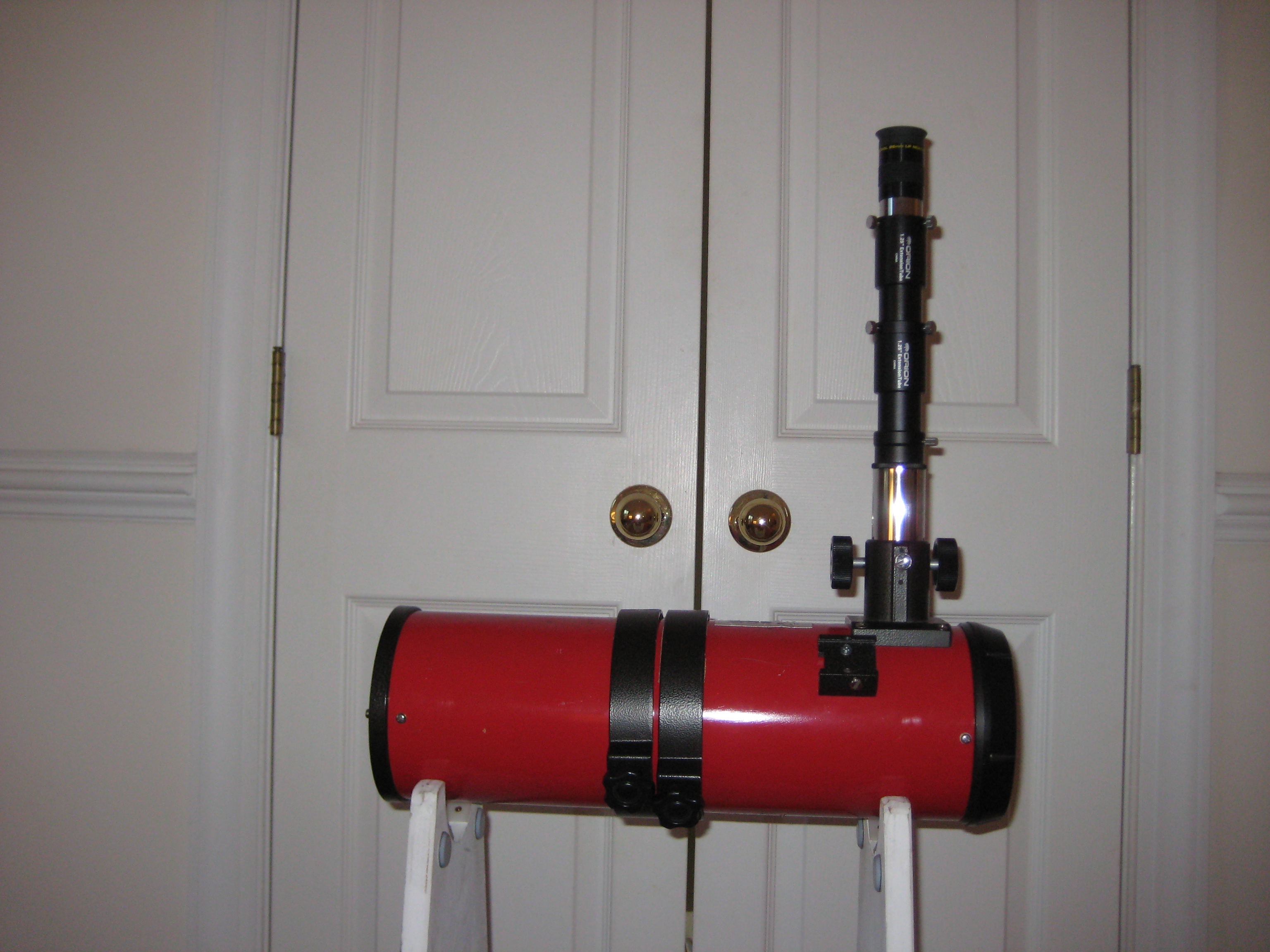
About this time I found out about Vixen 70001 extenders through a posting by Jae to Cloudy Nights [19]. Here's the photo [20] . These 70001 extenders are what you need to get height. They screw together (so don't wobble like the standard sleeve extenders) and having a large diameter, don't produce vignetting as do the sleeve extenders. Jae was kind enough to send me a spare 70001. Thanks Jae! It's the black cylinder (extender) between the chromed draw tube of the focuser and the Vixen 3720 36.4mm to 1.25" eyepiece adapter, in the two photos of the completed scope in the intro.
With Max's scope, I had the devil of a time trying to adjust the orientation of the primary using the adjusting screws. The primary moved erratically or not at all, and certainly not in response to my attempts to adjust the mirror.
There were 3 pairs of screws. Jim suggested I pull the cell apart to find out what was going on. The mirror was solidly glued to the back plate, as you would expect. He thought that I'd find that one of the pair was a pusher and one a puller, and I'd have to figure out which was which. It would be a good idea to put a spring on one of the screws, converting it to an adjuster, when the other would become the lock screw. Sure enough, that's what it was. The scope was designed so that to adjust the mirror, I had to simulateously adjust two screws; the pusher and the puller, in each of the 3 pairs. This was insanity.
I converted one screw to a spring tensioned adjuster screw. The other screw would be the lock screw, to hold the mirror in place. I expected I'd have to go on-line and wait for the springs, but my local hardware store had just what I wanted; springs that just fit over the screws. They were longer than needed, so I cut them down to length. To stop the cut end from bighting into anything, I folded it down with pliers and bent it inwards so that the spring gripped the screw and stopped the screw from falling out, on disassembly.
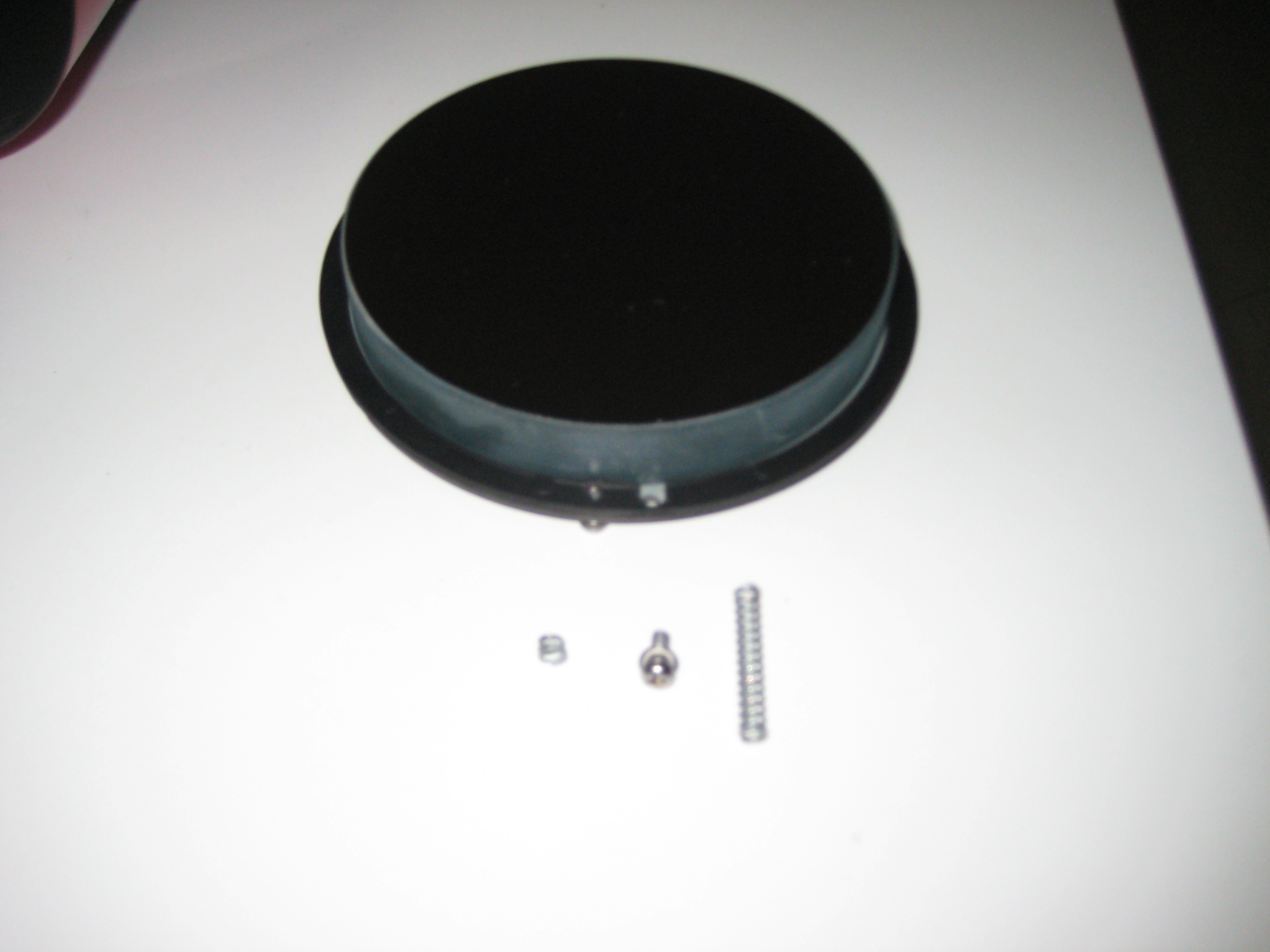
The photo shows the primary in the mirror holder. On the near side of the mirror holder is the site of a pair of screws. The left side is the locking screw. The adjusting screw has been removed and separated from its spring, in front of the mirror. An orginal length (uncut) spring from the hardware store is on the right.
Although I already had marked the mirror holder and mounting ring with marker pen, I needed further help to line up the screws with their holes, which became hidden as you joined the two pieces. Between messing around and aligning the scope, I wound up removing and putting back the mirror holder several times., I marked the locations of the screw holes on the outside of the mounting ring, so I could line up the screws with the marks and then push the two pieces together. Then the screws would just screw into their holes.
After inserting the springs, I found that one of the screws no longer bit the thread. Inspection of the cell showed that the first 4 turns of the thread were stripped. This is poor design - you can't hold the weight of a 125mm mirror in 4 turns of a 4mm thread in aluminium. The threads should have been designed longer or wider (see also tripod tray). I changed the screws to the longest that would fit the whole length of the thread. (They were about 30% longer than needed. I took up the slack with 6 extra washers on the outside of the back cover.)
I had read (Cloudy Nights?) that one fellow's primary was not adjustable for tilt. He had only 3 screws (not 6 as in Max's scope). He found no rubber gasket to fill the role of pushing the mirror against the adjusting screws. Milt's scope had only 3 screws. Adjustment of these did not affect the tilt either. Max's primary had been glued to the back plate. When I unscrewed the cell in Milt's scope, the mirror fell face down onto my work bench, covered in tools and screws. This was like opening up the scope to find a 30yr old turd left in there by Tasco. I was very lucky - the mirror missed everything. This is negligence. The mirror was not attached to the back plate or to the cell - it was just rattling in there. There was no rubber gasket pushing against the screws, and because the primary was not attached to anything, adjustment of the screws just moved the back plate, but not the primary. It was not possible to adjust the primary and it had never been possible. Tasco did not intend it to be adjusted.
I glued the mirror to the back plate.
Inspection of the mirror cell showed that one of the drillings, for the 3 screws from the back, was through the wall of the mirror cell. This would have been visible at the time of manufacture. I replaced the screws with long one and added springs on the screws sitting between the back plate and the mirror cell.
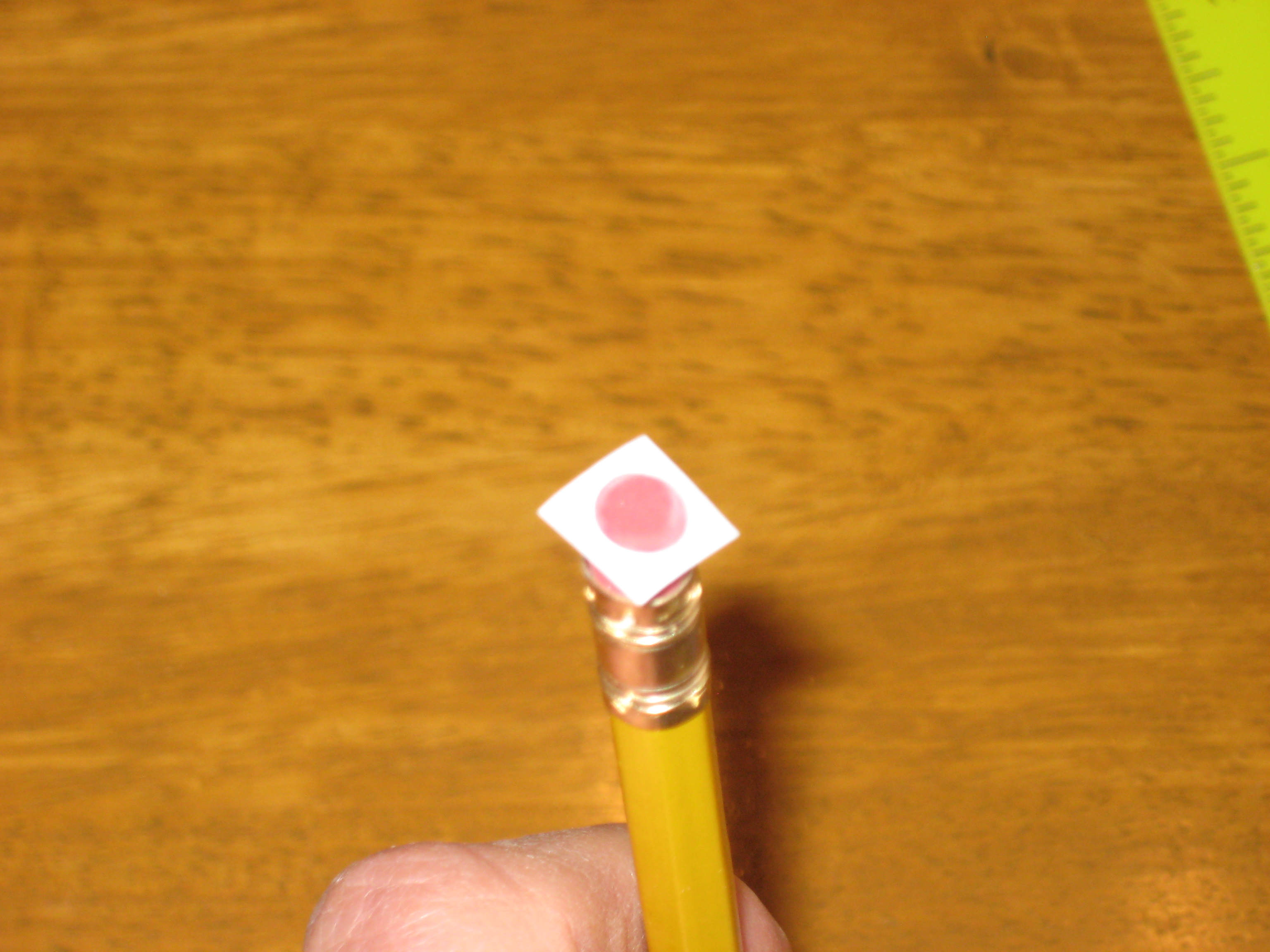
The first thing you do when collimating/aligning a newt is to adjust the roll and tilt of the secondary, to put the center of the primary under the cross-hairs of the cheshire. The center of the primary needs some distinguishing mark to identify its location. If the primary is even approximately adjusted, then behind the image of this identifying mark will be the image of the inside of the focuser, a uniformly black disk (if you have a cheshire in the focuser, you can illuminate it with a flashlight/torch and you will see a white circle in the middle of the focuser). The mark at the center of the primary must _not_ be a dark blob or you'll not be able to distinguish it from the inside of the focuser. I suggest the white self adhesive reinforcing rings, available at office supply stores. Even better, cut the outside of the ring to a non-circular shape, e.g. a square. If you use a barlowed laser (blug) for alignment, the image of this square ring will be projected back into the barrel of the blug.
To find the center of the primary, The usual procedure is to cut out a paper circle the size of the mirror, and cut out a hole in the center and lay the paper on the mirror and mark the center of the mirror with a marker pen. Somehow, I always wind up hitting the surface of mirror with the paper. Since paper isn't soft (it contains silica), I've stopped doing this. Instead I lay a soft (wood, plastic) ruler across a diameter of the mirror (you can find this by looking for the maximum size of the mirror) and marking a short line normal to the ruler. Rotate the mirror 90° and repeat. The center of the mirror is the intersection of the two marker pen lines. (The soft ruler contacts the mirror at at infinitely thin line. Laying a ruler across the mirror like this, won't affect the image as much as a paper scratch to the surface of the mirror.)
Because of some later confusion, when for a while I thought that the mirror wasn't centered in the OTA, I checked that the dot was in the center of the mirror, and at the center of the cell. It was.
Here's how I apply the square hole to the center of the primary.
 | Warning |
|---|---|
| This is not a particularly safe thing to do. The square ring landed correctly the first time. Repeating the exercise on the 2nd Tasco 8V, the ring flipped off the pencil, onto the wrong spot where it stuck. Fortunately there was a slight air gap in one spot. I had to do some careful surgery to move it with a box cutter, without scratching the primary. | |
I center the eraser over the central marker lines and allow the tilted corner of the square to touch the mirror. Then I move the square into place with the (blunted) point of the pencil, before tacking it down, by pressing lightly on the 4 corners of the square with the pencile tip.
Initial alignment with the laser, found that the dot in the middle of the primary was off by about 1/4". This is normally fixed by tilting the secondary or the focuser, neither of which I thought were adjustable on this scope. (As I found out afterwards, from a posting by Steve_M_M, see plate, the secondary has the usual adjustments.) I found by giving a judicious heave to the focuser that the laser dot now lined up reasonably well with the dot at the center of the primary (I wouldn't do this again, now knowing that the secondary is adjustable). Inspection of the outside surface of the OTA using reflection of daylight along the cylinder, showed no bumps or irregularities. Presumably the focuser was sitting on an undeformed OTA. Further heaving on a similar scale, didn't change the alignment any further.
I adjusted the primary to reflect the laser beam back to the laser. The alignment as viewed in the Cheshire, was sort of OK, but wasn't spot on and the more sensitive autocollimator showed that collimation was out of range. A defocused artificial star test with a 25mm eyepiece looked OK, but with a 10mm eyepiece, showed the scope not to be collimated. I was unlikely to be using a 10mm eyepiece on this scope. Did I care? Well yes I did. I'd come this far, I wasn't going to stop at this last step.
Jim suggested I use the star test, to iteratively adjust the primary (my only adjustment) to minimise the collimation error. I expected I'd have record the results and then shim the corners of the focuser (with pieces of manilla folder) and minimise again, till I found the minimum. Presumably it wouldn't be the exact minimum, but close enough.
Before I did this, with a near alignment, I wanted to check the vignetting. I did a few sweeps of the artificial star with my longest focal length 1.25" eyepiece (25mm). At focus I couldn't detect any vignetting. However even the dimmest of the 5 stars was bright, so this wasn't a good test. To look for vignetting, you want something that's just visible in the center of the FoV, and you watch for its disappearance as you move it to the edge of the FoV. In an attempt to dim the stars further, I defocused till one of the rings was quite dim. I swept the artifical star from side to side across the FoV to find to my surprise that the defocused rings changed shape. At the center of the FoV, the rings were circular and centered on the airy disk. As I moved the star to one side, the rings became elliptical, with the long axis pointing to the center of the FoV. The airy disk is at the focus of the ellipse nearest to the center of alignment. By adjusting the primary, I could circularise any elliptical pattern, offset from the center of the FoV, moving the center of alignment to this spot. Presumably I'm seeing uncorrected spherical abberation. I realised that until then, I'd made no attempt to bring the image under test, to the center of the FoV, this not being needed in a conventional Newtonian scope, which has little spherical abberation. Presumably the astigmatism I had seen was really spherical abberation, which I missed because I didn't undestand how the scope works.
Knowing that the scope was setup for 0.965" eyepieces, I had brought a 0.965" to 1.25" adapter (which will produce vignetting because of the obstruction) and some 1.25" eyepieces with me to Australia. However with the scope's dirty optics, there wasn't much point in doing anything beyond checking for obvious problems, by looking at the wires on the telegraph poles out the living room window during the day.
I wanted to use 1.25" eyepieces to take advantage of their nice optics, and to be compatible with my other scopes. The problems to be solved were
finding/making a 1.25" adapter for the focuser:
The 0.965" to 1.25" adapter restricted the field stop to much less than for a 0.965" eyepiece. Because of the resulting vignetting, I would be worse off, than just staying with the 0.965" eyepieces.
The ID of the drawtube was 1.5" giving sufficient clearance for a 1.25" adapter. The thread at the top of the focuser was very fine and I couldn't imagine making anything to match it. Presumably I could have someone machine up a block of delrin to jam in the top of the drawtube. It would be nasty but it would do.
Then one night, after several hours of googling, I accidentally came upon the exact adapter for this focuser for 1.25" eyepieces. It's Vixen number was 3720, it was the only one I knew of in the world and it had been in stock for 166 days (what did we do before the internet?). (As I later found out, these are available everywhere. Jim had expected that the scopes were designed for 1.25" optics from the start.) Since my scope was the only scope with these threads (as far as I knew), then this scope must have been available for 1.25" eyepieces. I bought the adapter on the spot, not being able to believe my luck. I waited for 2 weeks till the adapter arrived, to find it fitted perfectly. In the meantime I sweated wondering if after 166days, the company's inventory computer and the contents of the box on the shelf had got out of synch. The adapter had sat untouched for 5yrs before being sold. I couldn't believe that no-one had chucked it after all this time of it not moving. But all was well and now I had a perfect all-Vixen-parts 1.25" scope. I've spent my life making home-made things. They all work, but you have to remember things like when you disassemble this part, you have to put your finger here, or the screws drop on the floor. After a lifetime, this gets tiring. Sometimes you want it to work perfectly. I wanted Max's scope to work like new, and now it would.
vignetting:
When focusing at infinity, the eyepiece is at the highest point of the drawtube. The standard sleeve extenders reduce the aperture available to the eyepiece, causing vignetting on long focal length eyepieces. The larger diameter 70001 extenders that Jae showed were just the thing (see artificial_star). It seems that the Vixen scopes of this era had a large range of hardware for mounting cameras etc and none of it is available anymore.
Since making a scope for 1.25" eyepieces requires a bigger secondary and corrector lens than for 0.965" eyepieces, I expected that this scope would be setup for 0.965" eyepieces and the long focal length (> 20mm) 1.25" eyepieces would be vignetted. Jim was confident that the scope had been designed for 1.25" eyepieces even though it was sold with 0.965" adapters and eyepieces. I was most dubious. Manufacturers don't make scopes for 1.25" eyepieces, if they can sell the one for 0.965" eyepieces and the customer can't tell the difference.
To check, with the 1.25" adapter inserted, I lowered the draw tube to the height of the field stop, when focused at infinity, put my eye at in the draw tube and looked at the secondary. There I saw the reflection of the primary to the edge (or as Jim says "to the clips"). If I was going to get vignetting, I would see more than the whole primary (the eyepiece would be partially illuminated by the black inside of the OTA). As a check I measured the circular aperture on the secondary support, through which the rays from the secondary travelled to the focuser. This aperture is the projection of the secondary in the direction of the focuser. This was 22mm, about the field stop (21.2mm) for a standard 25mm 1.25" 50° AFoV eyepiece. It would seem that this scope had been designed for 1.25" eyepieces. Another stroke of luck!
The real test would be to look for vignetting with a long (25mm) focal length 1.25" eyepiece, first during the day and then on a star field. This would have to wait for alignment.
The scope is sufficiently small (125mm), that you're confined to bright objects and a finderscope isn't much use (I regard any finder scope of aperture smaller than a pair of binoculars, not worth using). You're better off looking directly at the sky, with a red dot finder or a laser pointer. These didn't exist when the 8V came out. The original 30*6 finderscope sits on a handy Synta shoe. I replaced the finderscope with a Synta shoe compatible green laser pointer (for observing on my own), and red dot pointer (for star parties). (Green lasers are banned at star parties. Astrophotographers don't want green rods crossing the sky in their images). Later, for observing the sun with a solar filter, I bought a Televue Sol Searcher with Synta adapter (QRD-1006) to use in the Synta shoe.
I couldn't find a laser pointer with a continuous-on feature. Mr ScopeStuff [21] explained that the FDA regulates these devices and you can only have a momentary-on switch. He says his green lasers operate down to about 5°C. He also cautioned anyone making a permanent holddown (e.g. a collar) for the laser button, not to crush the circuit board underneath. Don't jam the collar hard, don't turn a thumbscrew too much, and when the batteries are flat, don't push the button hard with your fingernails trying to get the laser to come on.
After getting the primary aligned on an artificial star, I had to wait another week for a clear night. With the mount in Australia and no suitable mount here, I sat on the front steps with the scope resting vertically on my knees. I got a good bead on jupiter at the zenith with a 25mm eyepiece. This is not a high magnification or a particularly exactlng test, but is what I expect to be using on the scope most of the time. From center to sides; the moons were points, Jupiter was a circle (and not an ellipse), and the line joining the moons stayed straight. There was no detectable vignetting or chromatic aberration.
The scope is a sucess!
When I get to Australia, I'll take a photo of the scope in its equatorial mount.
In the meantime, here I am with the mostly finished scope about 2 months later, at the Staunton River Star Party in Mar 2013, drifting on the sun. It was quite cold and a little bit windy.
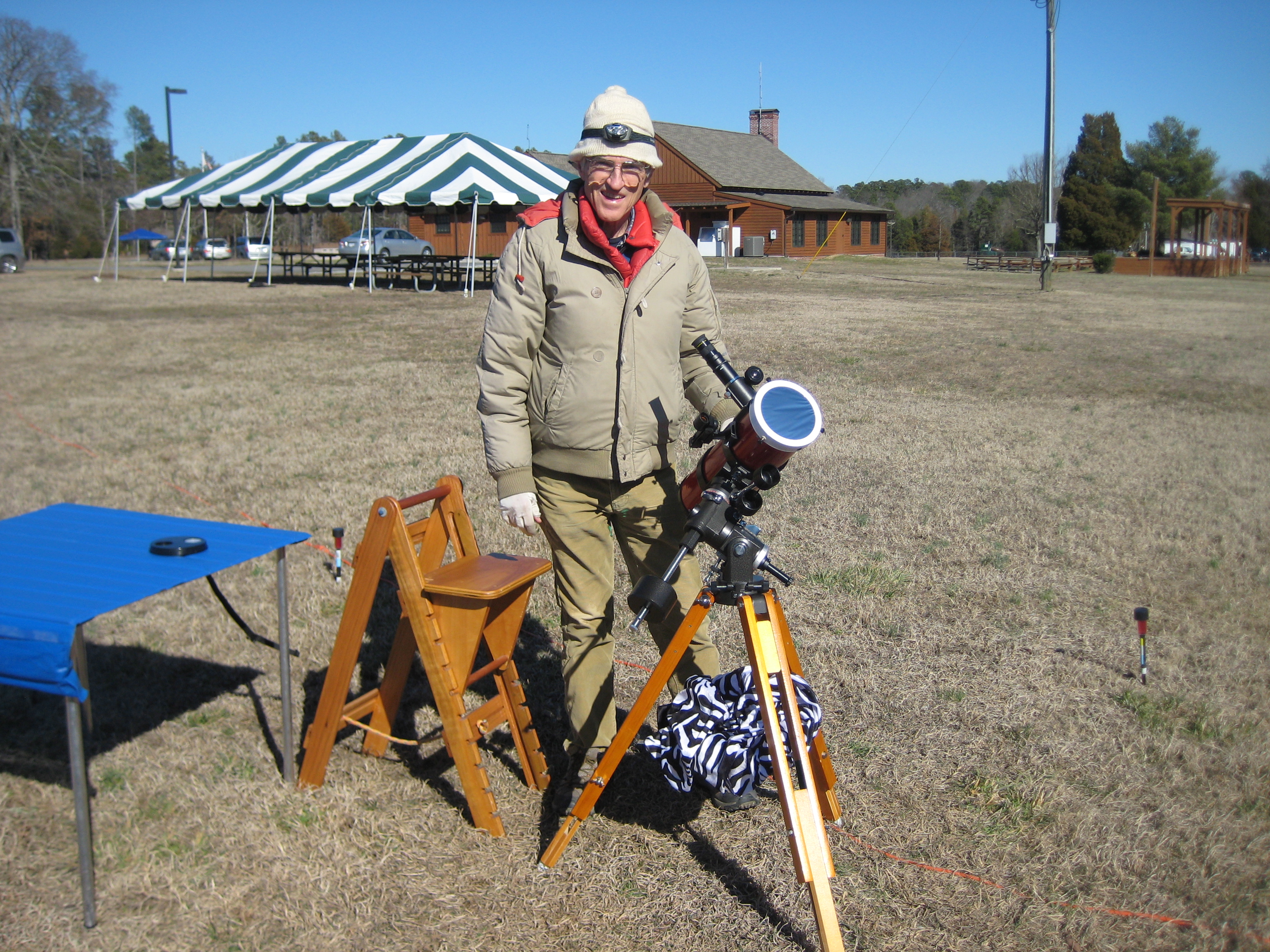
Note: the tripod legs are fully extended. It's still quite short.
The solar filter is from AstroZap. It's the AZ-1002 (136-146mm), with extra long screws to fit into 6 slots on the outside of the 130mm plate. If you're going to get one from AstroZap, make sure you get one that has the screws at 120° spacing. The one I got had the screws as an isosceles triangle, rather than an equilateral triangle and I had to return it.
On spending some time with the scope at the star party I found
- The field isn't flat. You have to focus separately for the edge of the field.
- The field has pincushion. Moving the sun to the edge of the FoV shows the part of the sun at the edge enlarging and being drawn out towards the edge.
- Chromatic abberation. Jupiter has yellow and violet edges.
None of these are a surprise.
Now I had an OTA in reasonable optical shape, but I didn't know how it fitted onto the mount (the mount was in Australia and I'd not taken much notice of it, being more concerned with the optics). I was afraid I could arrive in Australia and not be able to couple it to the mount and have to wait another 2yrs before I could use it. As well I'd never used an equatorial mount. Since the scope was good enough to use in Australia, I decided it was good enough to have one here in the US too. The solution was to get a duplicate Tasco 8V with mount, for USA. I could test Max's scope on the mount and then take it with me to Australia, and have a duplicate back in the US. I found one in good shape on Cloudy Nights, being sold by Milt Hays, who also showed me the fix for locking down the OTA (see Milts blocks). It arrived in perfect shape; even the plastic caps for the Polaris scope and the finder scope were included, along with the manual. Unbelievable that they still exist after all this time. I bought a Vixen 3720 1.25" eyepiece adapter for it.
Milt's scope was well aligned and I didn't mess with it till later (when I pulled it apart to put springs in the primary adjusting screws etc). Testing it on Jupiter and the Pleiades with a 26mm eyepiece (mag=40), on the steady equatorial mount, I swept the objects from side to side across the FoV. I noticed some chromatic abberation on Jupiter, which I'd expected. As well I noticed pincushion, which I hadn't noticed when I balanced Max's scope on my knees. You have to expect pincushion or some variant of it. This is not modern optics and the simple two element J-B corrector design dictates some compromises. I wanted a small portable scope to use with long focal length eyepieces. (Milt tells me this is called a Rich Field Telescope. I just thought it was a scope with a wide FoV.) The performance was in spec as far as I was concerned. If I want perfect optics, I'll get out my unwieldy zerodur Dobs.
I set about finishing Max's OTA, making Milt's locking wooden blocks for it.
Three parts of the secondary mount require a pin-type face spanner [22] to disassemble/unscrew/remove. You'll be using the face spanner near the glass plate. If you think you might slip, cut out some thick plastic (e.g. a ziplock bag) and tape it to the plate. You may have to clean your plate later. This is easier than removing a scratch.
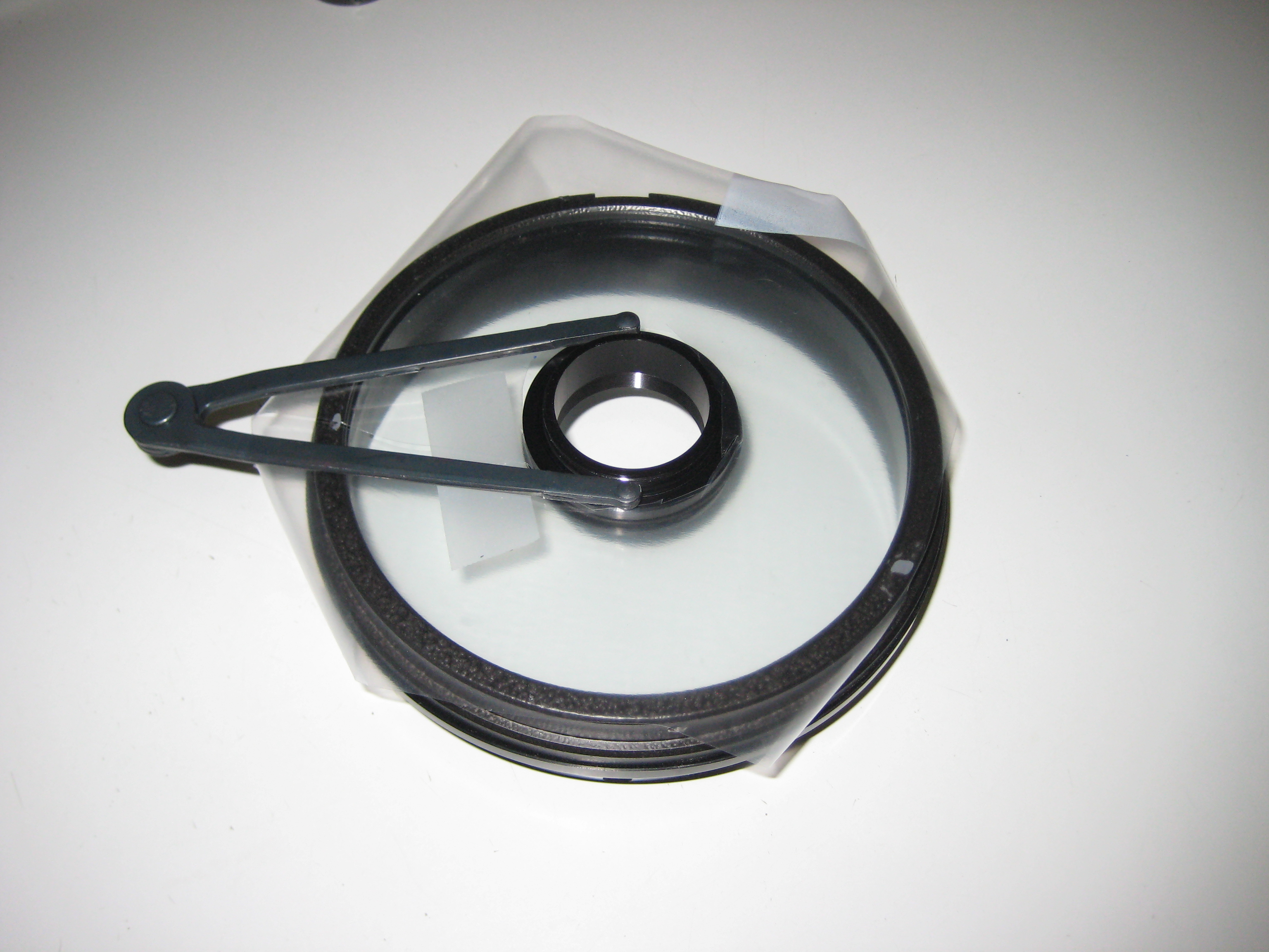
My face spanner does not have enough inside clearance, to fit into the pin holes and clear the threads on the secondary mount (into which the secondary stalk is screwed). I filed down the inside of the jaws of the pin-type face spanner to fit. This photo shows the plate with the corrector lens removed.
I used plastic gloves to avoid leaving fingerprints on the optical surfaces. As you can see in the photo below (secondary, cap removed), when I was finished, there are white patches on the OTA. I'd forgotten that the gloves were dusted with talc, which helps when removing sweaty hands from gloves. Talc is fine for working on cars. I just grabbed the gloves I had in the garage. For optical work, it would be better to use talc-free gloves, or at least first wipe off the talc.
The grey coloured intermediate sized annulus has three grub screws (M3x0.5, 1.5mm hex key) in the plane of the plate, which adjust pitch and yaw on the secondary.
One of the threads was tight enough to make alignment difficult. The opening for the thread was blocked so that I couldn't remove the grub screw. A drop of oil didn't help. Presumably the outer part of the thread in the aluminium body had problems. For the alignment, I didn't need to remove the grub screw, but I wanted alignment to be easier. With the secondary stalk out of the plate, I screwed the grub screw all the way in, allowing the outer part of the thread to be chased with a M3x0.5 die. I then removed the grub screw and chased the whole thread with the die. I cleaned the swarf with greenhouse gas blaster.
I was not happy to be using a hex key in close proximity to glass. Reinsertion of a standard (straight ended) hex key required some jiggling, a slow and accident prone process. Here are my solutions to the hex key problem (best to worst)
The best solution for day to day use is the ball headed hex key (next section). However restoration required pulling the secondary stalk out multiple times, followed by realignment. I needed a temporary, but more convenient way of aligning the secondary. I replaced the M3x0.5 grub screws with (hex headed) cap screws. This allowed me to align the secondary without tools (with just my fingers, on the caps of the cap screws). I used the longest screws available (18mm) to clear the outer locking ring. The cap screws occlude the optical path and prevent use of the secondary dust cap i.e. they can't be used permanently.
Note note the fender washer, between the wooden block and the screw thread, in the mounting ring lock. Before putting the scope back into service, I replaced the grub screws and realigned the secondary again.
Use a ball headed hex key, which goes into the grub screw first time every time. Unfortunately these are only available in long versions, too long to fit into the secondary mount when it's in the plate. The solution was to bend the hex key. They snap if bent cold (guess how I know), so I heated one on a stove and then could bend it with pliers.
Here's the modified ball ended hex key, sitting next to the secondary stalk. Note the grub screw hole on the bottom of the stalk, facing the viewer.
In the meantime, while I was waiting for the ball ended hex keys to arrive, I filed down the end of my straight hex key, so that it was conical (or a hexagonal pyramid). This was better than the straight ended hex key, but not as good as the ball ended hex key.
To reduce the amount of jiggling with the straight hex key, which risked flipping the hex key into the glass, I only moved the screw between -30° to +30° positions, so that the grub screw would have a known orientation, when I tried to reinsert the hex key.
| Warning |
|---|---|
| This is a nightmare. Read the whole section before committing yourself to disassembly. There are many things Tasco did, that could have been done properly at no extra cost. The would have had to deliberately think of how to do it the wrong way. | |
I didn't attempt any adjustments on the secondary till after I'd completed the restoration of the plate and primary and done a star test. The collimation at the secondary was good enough for the Tasco optics, so for the moment I just optimised the tilt of the primary. At the time I thought the secondary was fixed at the factory and couldn't be changed. (I was right, it was glued into position, but I would never have guessed it was glued.) Then I saw a photo of the secondary with the cap off (I think from a Cloudy Nights forsale notice for a Tasco 8V carcass) and realised that in principle something could be done. A bit later, when looking down the axis of the OTA of the restored scope, I saw there was no viewing angle from which the internal bits were symmetrical. As well the cheshire showed obvious problems. I contacted Milt to find he'd had a go at it. So had others; here's a posting by Albert1 at Cloudy Nights, describing the disassembly of the Tasco 8V secondary [23] and a photo of the parts [24]. Clearly the secondary was within reach of the amateur.
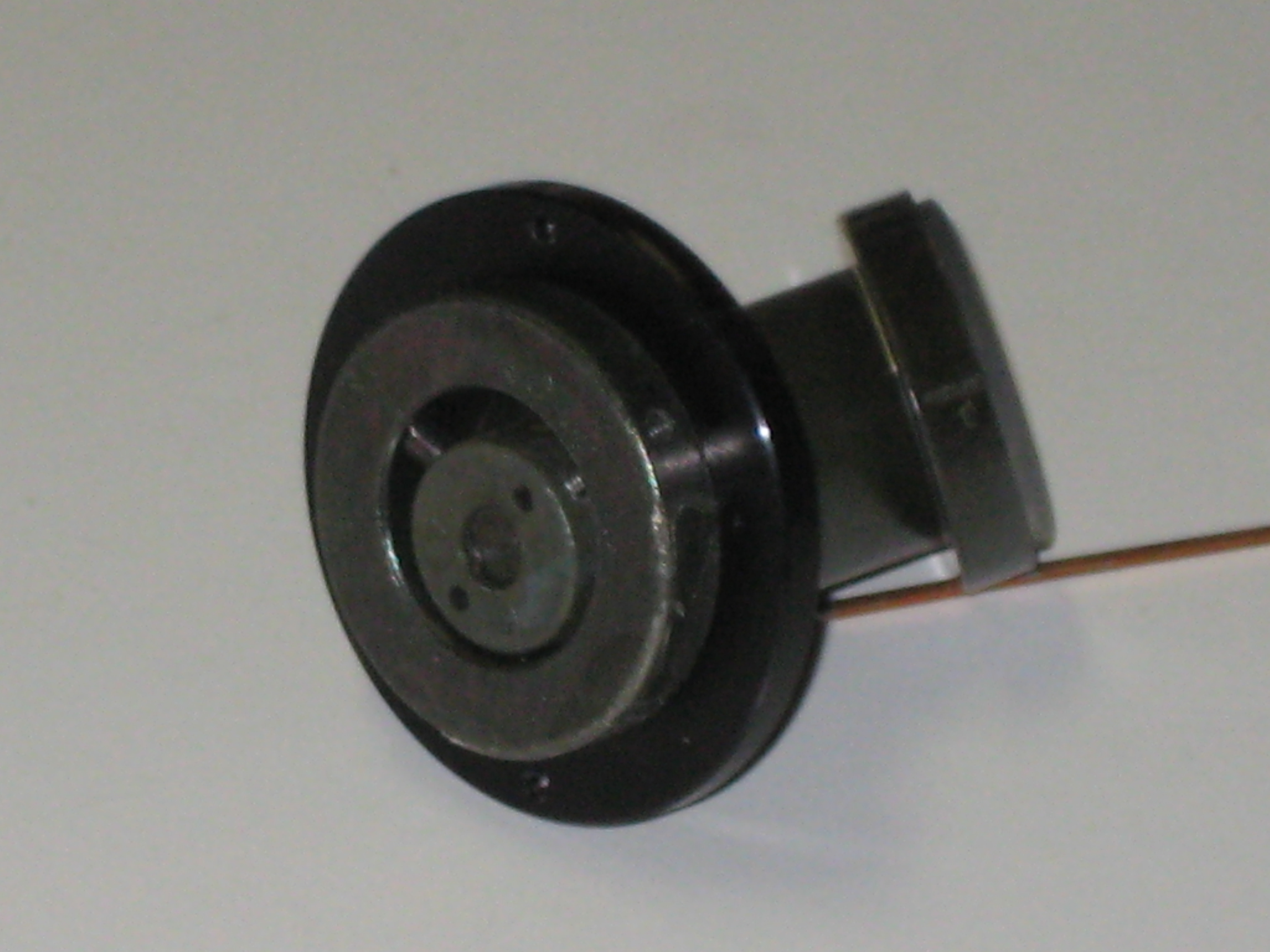
The secondary adjusting grub screws are accessible after removing the secondary cap (a standard plastic lens cap). Mine secondary cap was quite tight and needed the extra grip of plastic gloves to twist it off. Here is the view with the cap removed. (the photo here is taken after reassembly, when you can see the talc powder.)
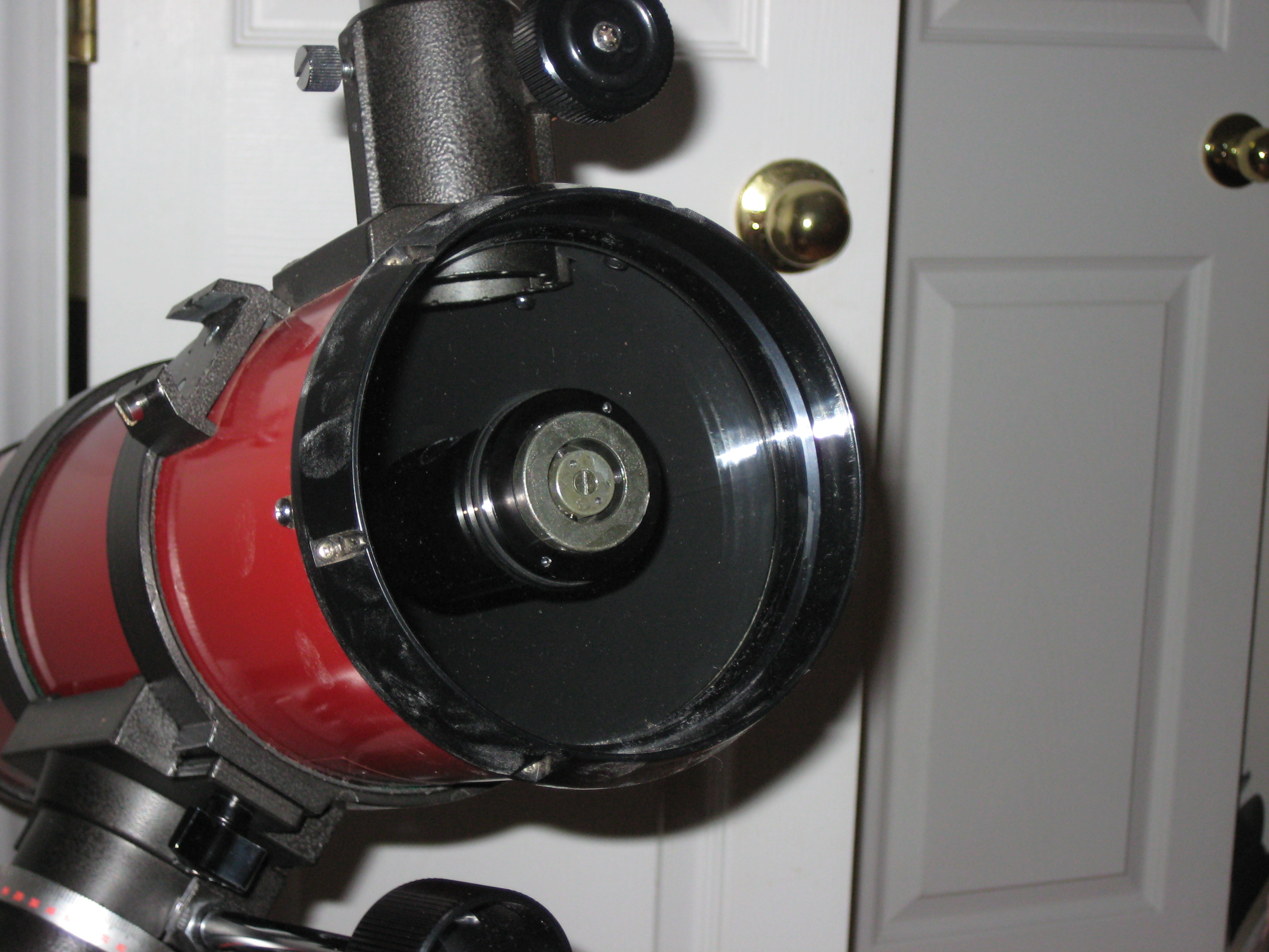
Note:
talc all over the OTA
An outer black ring on the secondary mount
This has a pair of 2mm holes (at 1 o'clock and 7 o'clock in the image) for a pin-type face spanner. The ring is used to lock rotation of the secondary mirror stalk. On my scope, this outer black ring was only finger tight (with the extra grip of plastic gloves) and could be unscrewed by hand. When the time came to unscrew it, not knowing what would happen, or what was attached to it, I first removed the plate from the scope, in case I had to catch pieces falling.
An intermediate grey annulus on the secondary mount. This has 3 metric grub screws (1.5mm) in the plane of the plate.
I assumed the purpose of grub screws is to adjust the secondary (it is), but initial attempts to fix the alignment, using the monkey-typewriter-sonnet principle, as viewed through the cheshire, failed. (I had assumed the grub screws translated the secondary stalk. They don't, they change its tilt.) In order to understand how the secondary mount worked, I removed the plate and unscrewed the outer ring, separating the secondary stalk.
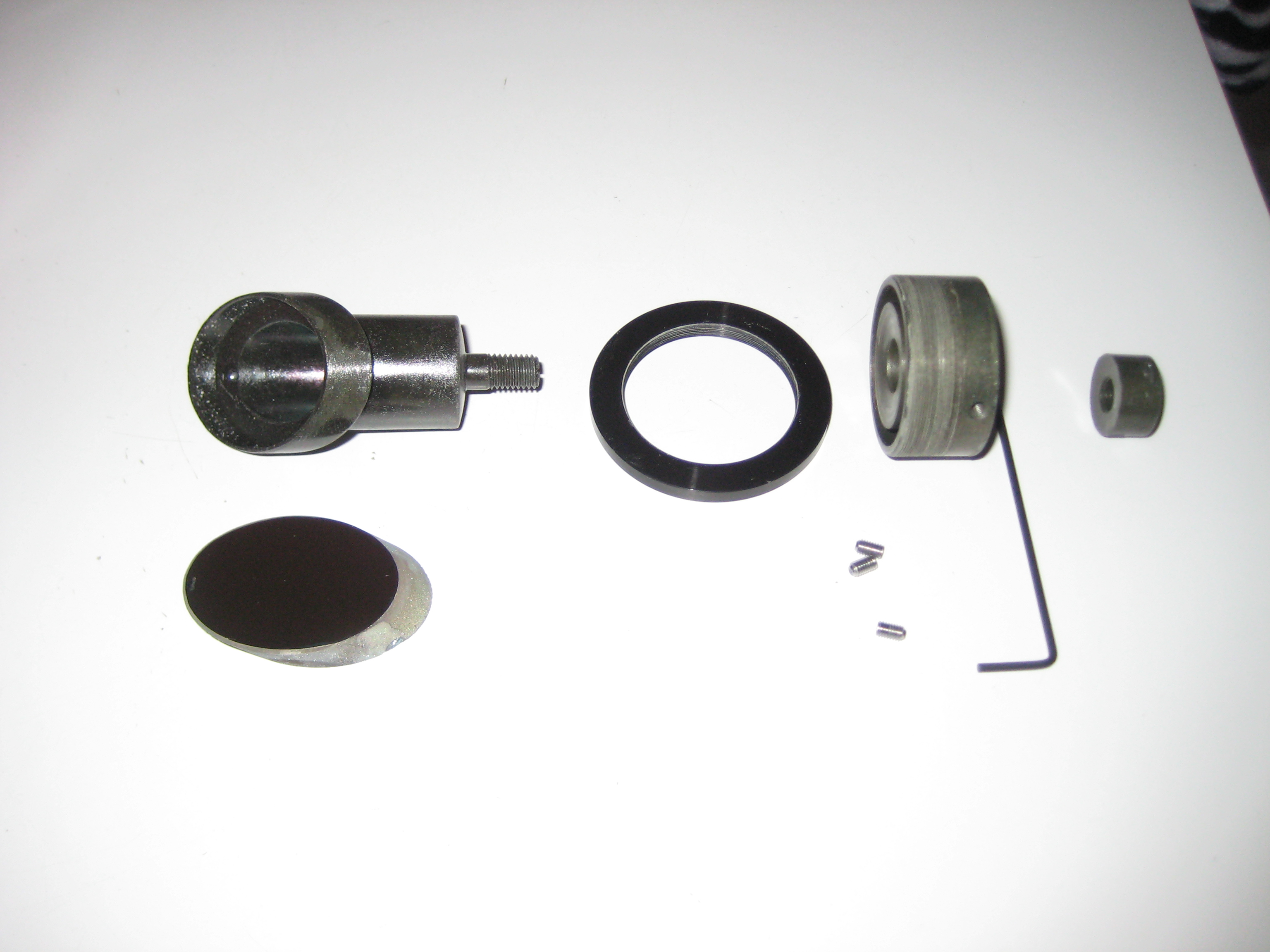
Here is the plate at furthest disassembly.
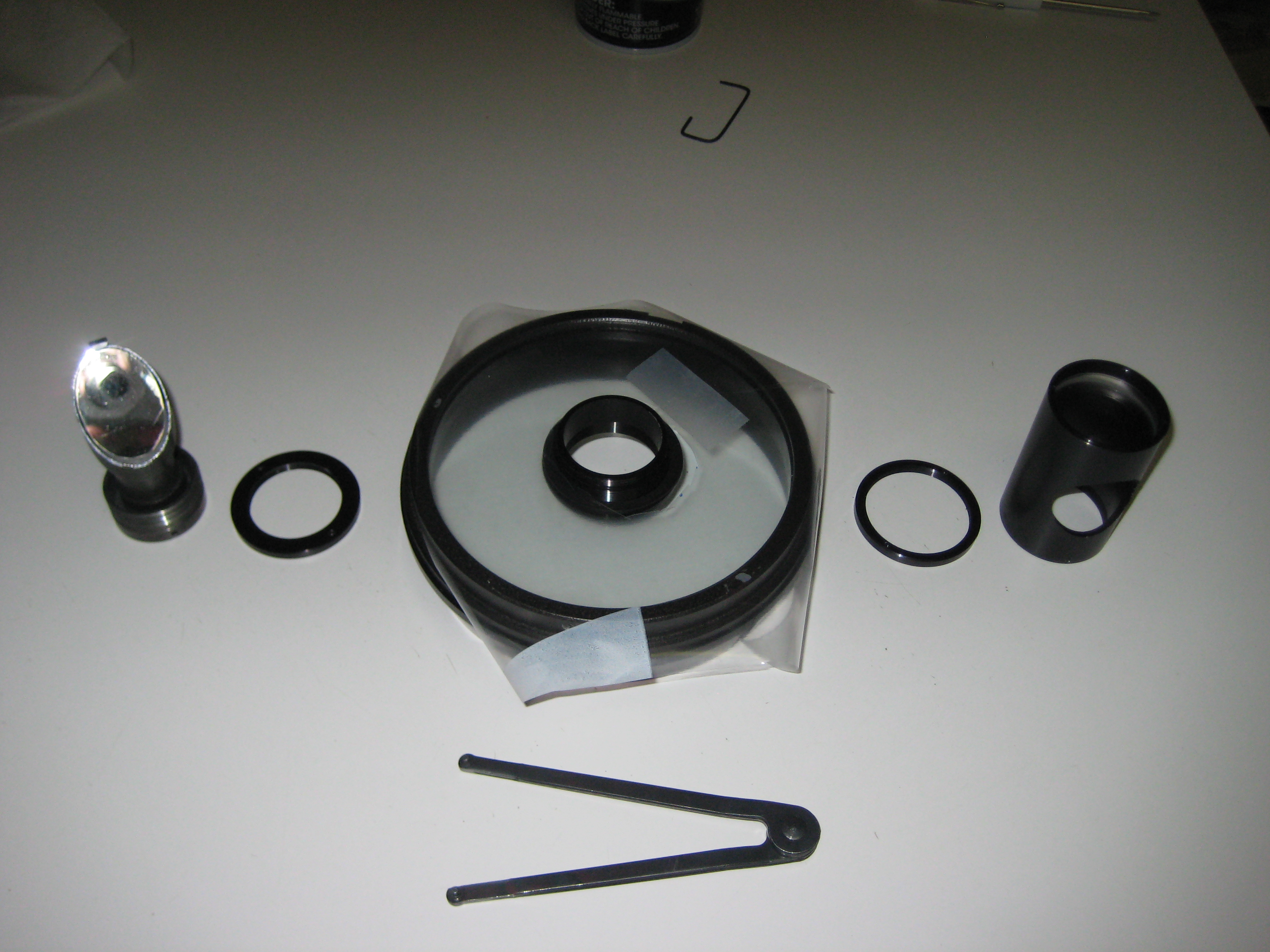
Left to right the pieces are
- secondary stalk - secondary mirror on top, ball and socket for swiveling the stalk in the base (see below). Underneath are 3 grub screws for pitch and yaw, slotted blade for roll.
- outer locking ring (holds secondary stalk in place on outside of plate)
- plate (covered with plastic to protect it from the pin-type face spanner), with secondary mount
- inner locking ring (holds secondary mount to plate on inside of plate)
- corrector cylinder (has corrector lenses on top, the aperture for light exiting to the focuser in the middle, and an inside thread at the bottom for attaching to the secondary mount)
In front: pin-type face spanner for locking rings and for inner annulus on underside of stalk.
This photo show the plate after unscrewing the secondary mirror stalk.
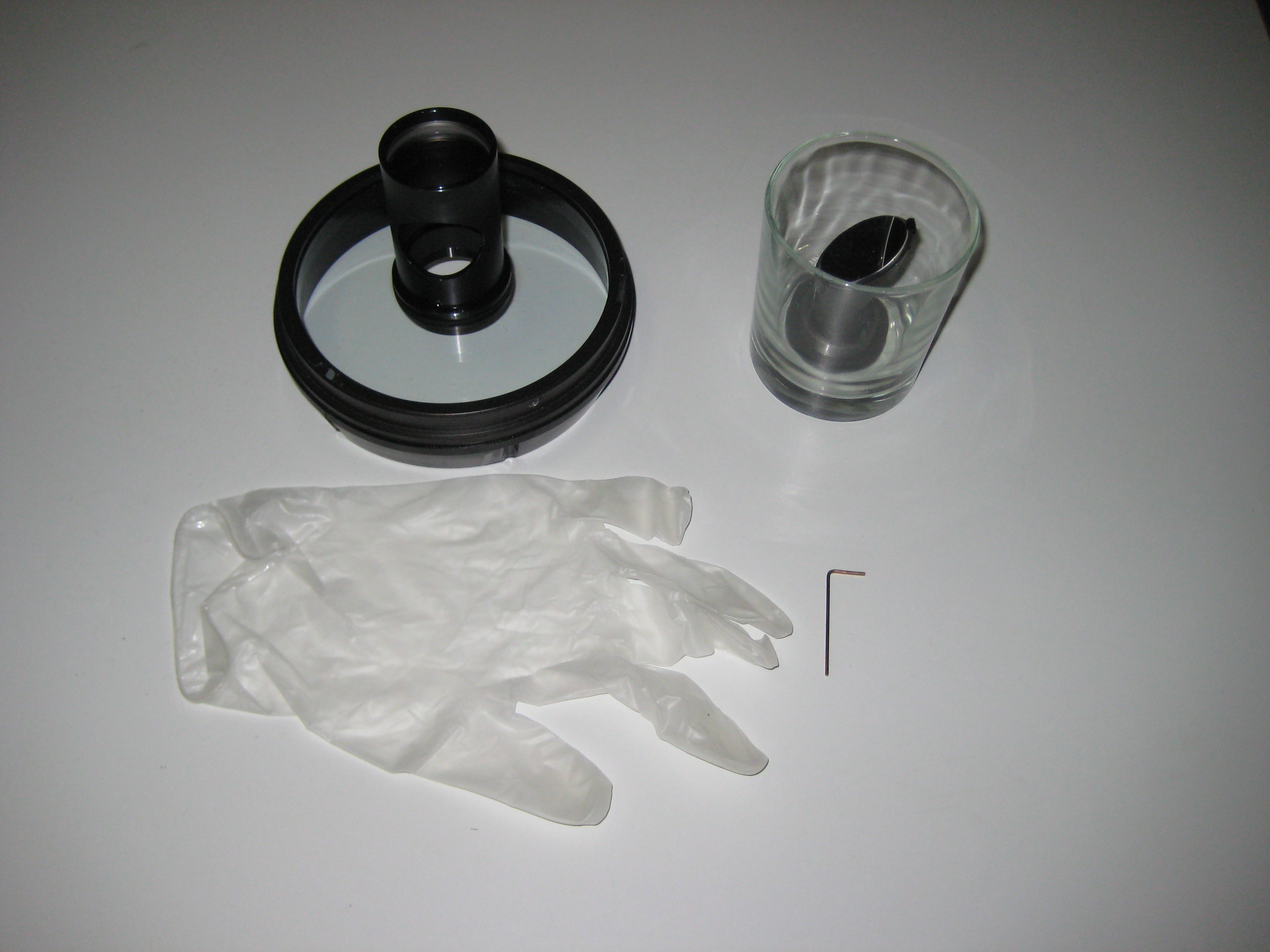
From top left, going clockwise
Plate with corrector lens assembly still attached.
Secondary mirror stalk in drinking cup.
The stalk sits up by itself. The cup was only there to transport the stalk to the hardware store, without it rolling on the floor of the car. I wanted to find a tool to undo the rings. I found that the tool is called a pin-type face spanner. They weren't available locally. I ordered one on-line (see "Tools" above).
1.5mm hex key
plastic glove (with talc - it's better to use gloves without talc)
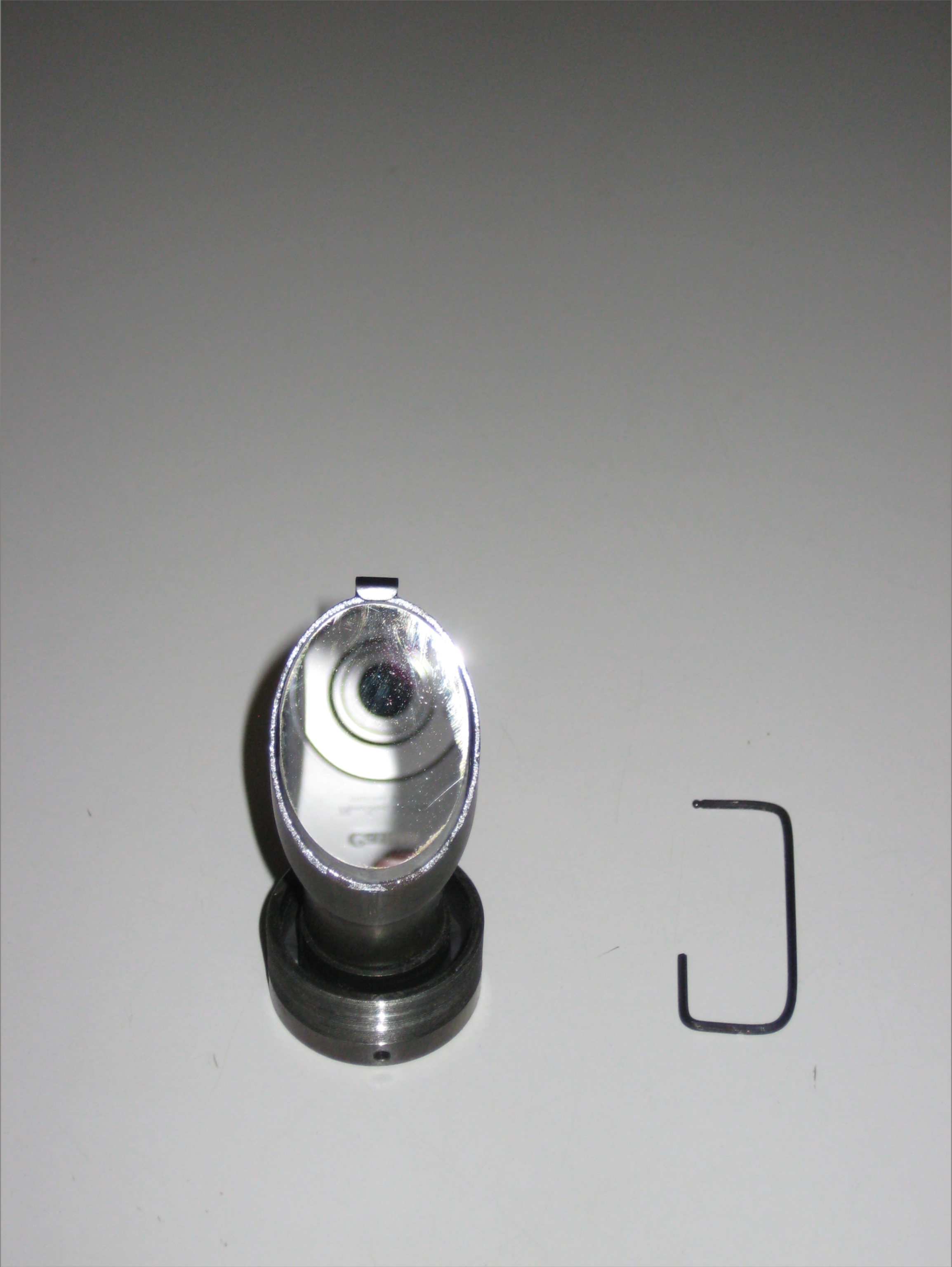
Here's the secondary stalk
The perspective foreshortens the secondary stalk. The hex key is to stop the stalk rolling over, which would put the mirror face down. The photo shows
The outer ring (black)
This screws onto the secondary stalk and locks it in place, by pushing up against the plate. It has 2mm pits, for locking with a pin-type face spanner.
The intermediate sized annulus (grey).
This is the outside end of the secondary stalk assembly. This is threaded on the side facing away from the camera. The thread takes the outer ring and screws into the outer end of the secondary mount. The annulus has 3 M3x0.5 grub screws for adjusting the inner annulus.
The inner grey annulus
This has a pair of 2mm pits for a pin-type face spanner. The annulus is moved eccentrically by adjusting the 3 grub screws in the intermediate annulus. For this photo, I have offset the centre of this annulus by adjusting the grub screws, to show how the inner annulus moves within the intermediate annulus. You will never need this much adjustment for alignment; only small offsets are needed. After alignment, you should expect the rings of the secondary stalk to be nearly concentric.
At the center of the annulus is a blade type screwdriver slot. The slot is for rolling the stalk (and secondary mirror) when doing alignment. (This is it's only role. It took a while to find this out. In the meantime, I was assuming it was to be used to help remove the inner annulus. It's not.)
The three grub screws tilt the secondary. It works this way
The stalk has the secondary mirror at one end.
At the other end of the stalk is a slightly convex surface. This surface fits into a matching concave surface on the back of the grey intermediate sized annulus, making a ball and socket type connection. This arrangement allows the stalk to be tilted in all directions and to rotate about its long (roll) axis. The centre of curvature of the matching surfaces is the centre of the secondary mirror. Thus the mirror can be rolled, pitched and yawed, without moving the centre of the reflecting surface.
The centre of the stalk at the convex (ball) end, has a smaller threaded section which fits through a larger hole in the concave socket end. This threaded end pokes out through the outside of the secondary mounting assembly and can be seen from the front of the telescope. It has the blade slot visible at the center of the inner annulus. This slot allows the stalk to be rotated (moved in the roll axis) endlessly about this axis.
The threaded section ending in the blade slot, would normally be terminated in a hex nut. However the stalk has to rotate around the roll axis, so instead of a hex nut, a circular nut, with pits for a pin-type face spanner, is used.
The three grub screws allow the stalk to be moved in pitch and yaw. The centre blade slot allows the stalk to roll (after loosening the grub screws). The slot is at right angles to the plane of the secondary mirror allowing you to approximately adjust the roll from the outside of the scope.
Here's the secondary stalk disassembled. This was the last thing I figured out how to do. By the time I got here, I'd already figured out how to remove the secondary mirror.
While working on my first Tasco 8V (Max's), I couldn't find any way of further disassembling the secondary stalk. Doing so, I'd hoped, might show me a simple path to fixing the longitudinal offset problem of the secondary mirror (see longitudinal adjustment). (As it turns out, further disassembly didn't help. I reglued the secondary mirror instead.)
The inner annulus/slotted blade were frozen together. (Liquid Wrench didn't help, but then was not expected to, since the frozen surfaces weren't rusted iron.) Presumably one screwed into the other. Depending which screwed into which, you would unscrew the slot one way or the other, while holding the annulus with the pin-type face spanner (I was wrong; they were glued together). I tried both ways. A major problem with this approach was that the slot was narrow enough for only smallest screwdrivers. The small screwdrivers aren't wide enough to exert any significant torque. The screwdrivers that match the length of the slot are too wide for the slot and tear out the slot walls. If you're going to have a screwdriver slot, at least have one that fits a screwdriver, or better have a hex head which won't tear out.
The mystery, of unfreezing the joint, was solved by accident. My 2nd Tasco 8V (Milt's) was perfectly aligned, but I changed the inside nuts to aeros (nylocks) on the Synta shoe, and the focuser. While I had the scope open, I put a square ring in the center of the primary. Naturally the scope was now misaligned. On attempting to align it, I found the secondary stalk was stiff, sticky and difficult to adjust. It felt like it had been glued in. The outside surfaces of the secondary mount were covered in a varnish, which felt like glue. I soaked the base of the secondary stalk in a (glass) cup of acetone for 3hrs, to find that all pieces were now finger loose, including the inner annulus. In the meantime, before I discovered this, my efforts resulted in a badly torn up slot on Max's scope.
From this discovery, I saw that the slot is only to rotate the secondary mirror on alignment. It is not to be used to separate the inner annulus from the secondary stalk. Tasco had glued them together and didn't expect anyone to attempt to separate them. In this case the slot should have been small enough to indicate that only a small screwdriver was to be used. Poking a blade type screwdriver into the front of the OTA in proximity to the plate is not a good idea. Better would be a Phillips head or a hex head.
After successfully unfreezing Milts secondary stalk, I repeated the process with Max's secondary stalk. It wouldn't budge after 1 day in acetone, but after 2 days, could be screwed off, with the help of the pin-type face spanner. The threads were covered in sticky glue, which dried and hardened as the acetone evaporated. I removed the dried glue by repeated threading and unthreading of the annulus onto the secondary stalk.
Note the curved surfaces on the base of the secondary stalk, the top of the intermediate annulus, and the top of the inner annulus. (There is a curved surface on the outside of the intermediate annulus which fits the inner annulus, but it's hidden in this photo.)
There was no obvious way to affect the longitudinal offset of the mirror by shimming the base of the stalk.
On reassembly, there was nothing to hold the inner annulus (the circular nut) onto the thread at the end of the secondary stalk. It rotated freely and moved with the adjustments necessary for alignment, when you wanted it not to move. My first attempt to solve this was using a 7mm wavy washer on the thread. This provided too much tension. On tightening the inner annulus enough to stop it spontaneously falling off the thread, it became difficult to move the inner annulus with grub screws. The wavy washer worked, but not well. I tried a 5/16" ID neoprene washer instead. Being rubber, it provided friction to stop the stalk from moving around. The extra friction meant that less tension was required to stop the inner annulus from spontaneously falling off the thread, so less force was needed on the grub screws when moving the inner annulus. The inner annulus now projects out of the scope (is no longer flush with the end of the secondary mount), but it's better than gluing it in position.
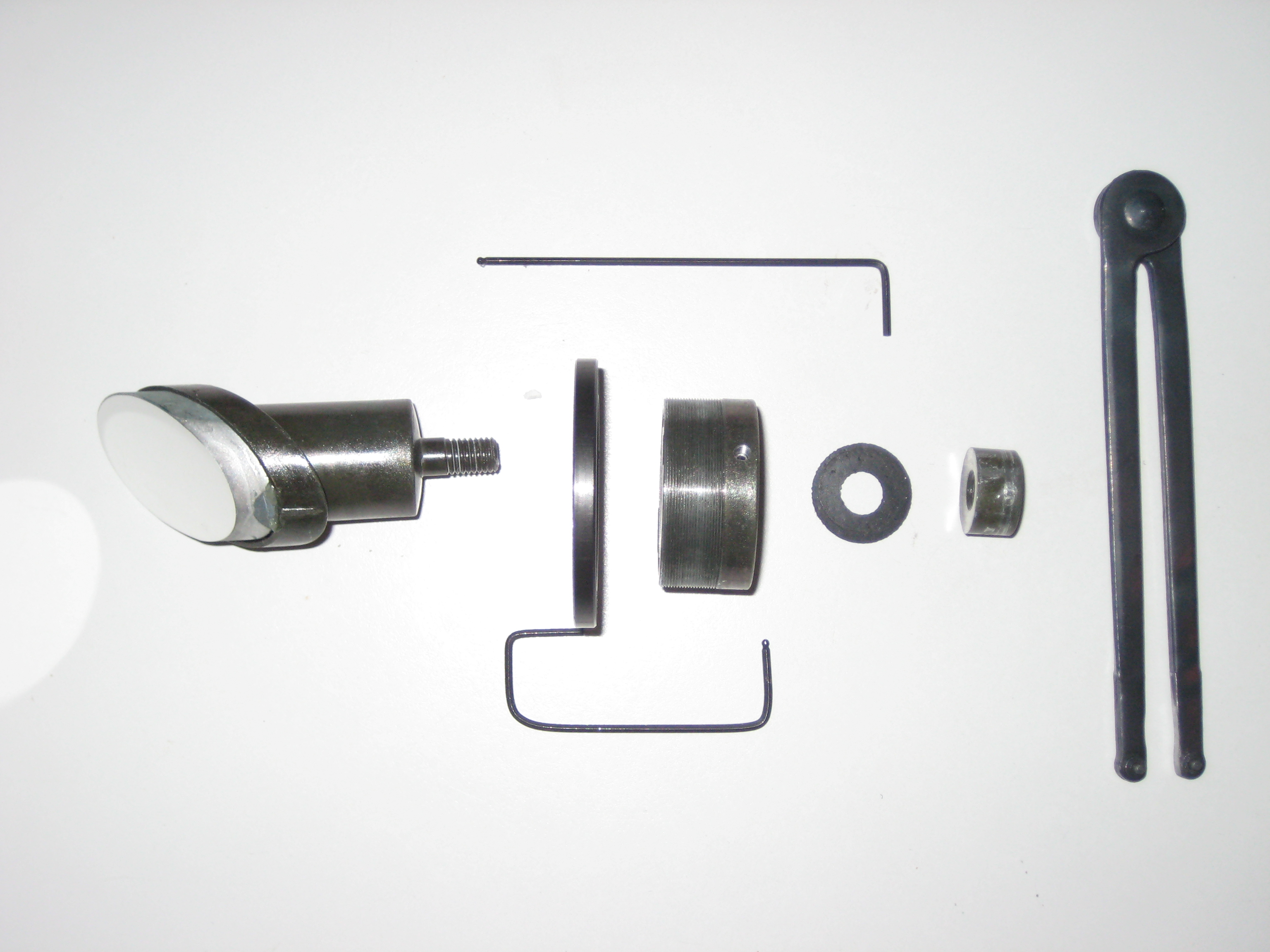
- top: straight 1.5mm ball headed hex key
- middle: L-R secondary mirror on stalk, outer locking ring, intermediate annulus, neoprene washer, inner annulus, pin-type face spanner (2mm pins)
- bottom: home bent 1.5mm ball headed hex key
This is a complicated device. I'd be OK with a complicated device, if they'd spent the extra dollar to make a brake for the OTA, which didn't crumple the OTA. Clearly there were separate budgets and design teams for the OTA mounts and the secondary mounts. The secondary design has the following problems
Without disassembly, its working is not transparent to the user. Telescope alignment (collimation) is a routine operation and cannot require disassembly to understand. If you're going to design something that you expect to be in use for a while, then its workings have to be obvious by inspection, and it has to be able to be serviced by the owner.
It's held together with glue making its operation even harder to figure out. Car engines hold together without glue. This scope should be able to too. Even when loctite is used on a car, a suitable grade (red, green, blue) is chosen, so that the joint can be broken by appropriate tools.
The adjustments are done too close to the plate using dangerous operations. e.g. the adjustment of the roll of the secondary is done with the sharp end of a screwdriver facing the plate. Even if they had to do it this way, they should have used a Phillips instead, allowing more secure placement of the screwdriver, and less likelihood of slippage. As well the grub screws have to be manipulated by a hex key close to the glass. This design should never have gone out the door. These people presumably don't wear seat belts, wash their hands before meals or engage in safe sex. Don't let these people design tools, medicines or space shuttles. It's possible to safely adjust the secondary from outside, e.g. the design by Protostar [25] (no connection, just a happy customer).
The fit of the curved surfaces isn't terribly accurate. The pieces aren't machined. Maybe they're stamped. The ball and socket joint has arthritis (movement isn't smooth) and not all positions can be reached. The circular nut on the end of the thread is not circular (it's bumpy) The grub screws have to be backed off to allow rotation of the stalk. If you're going to have an obtuse and complicated design, at least implement it properly.
The range of motion of the ball and socket is huge compared to any conceivable adjustement.
In my scope, as expected, the aperture (on the corrector cylinder) is centred in the cheshire. The cheshire looks through this aperture, to the secondary. The projection of the secondary should also be in the center of the cheshire's field. However, in my scope, the secondary is offset 3mm out of the OTA. The edge of the secondary is occluded by the aperture. This could be fixed by screwing the secondary stalk into the OTA, but it's already at its innermost limit, up against the plate. If you wanted to, you could move the secondary out of the OTA by unscrewing the secondary stalk and relocking it with the ring, but this doesn't help with the current problem.
| Note |
|---|---|
| My second Tasco 8V has the secondary offset longitudinally by about 1.5mm. It only just fits into the aperture facing the focuser. | |
This occlusion of the secondary mirror causes vignetting, but doesn't prevent alignment. When the scope is aligned, not all of the primary is seen by the secondary, and part of the secondary is looking at the inside of the OTA.
You cannot adjust the secondary longitudinally into the OTA, requiring modification of the scope to fix the problem. You would expect that removing the locking ring entirely would allow you to screw the secondary stalk into the secondary mount, by the thickness of the locking ring. However there is only a couple of extra turns of thread on the secondary mount. This doesn't get you very far into the 3mm offset and was abandonned as a solution.
| Note |
|---|---|
| When screwing in the stalk, without the outside ring, do this with the plate out, so you can watch the end of the secondary mirror as you screw it in, as if moves towards the corrector lens. You don't want to accidently screw the secondary mirror into the corrector lens. | |
This uncorrectable 3mm offset of the secondary shows abysmal QC at Tasco/Vixen.
A possible fix would be to remove the secondary mirror (presumably destructively, since it's glued down), and put a pad under the new secondary mirror to move it further into the OTA. Inspection of the secondary mirror holder, showed that it was recessed; the glued surface is not accessible and you can't even get a razor blade under it. This contravenes on of the big rules of making something - it must be able to be serviced, particularly if you aren't going to make it right the first time.
| Warning |
|---|---|
| Using Si glue is not a good solution. The solution here was my first attempt at the problem. The Si glue is sticky and when applying it I wound up getting it on the front surface of the secondary mirror. I couldn't get it off without risking scratching the mirror. The Si glue is not reversible; if you don't like the job, you're can't remove all of the Si glue from the back (or sides or front) of the mirror and you're stuck with it. I would suggest (but haven't tested) the clear double sided sticky pads from office supply stores, that are used to stick posters onto walls. These are easy to peel off, but I don't know how well they'd be for a decade inside an OTA. Would the secondary mirror fall off one day? | |
To solve the longitudinal offset problem (see longitudinal adjustment), I had to move the secondary mirror into the OTA. This required removing the secondary mirror and repositioning it further into the OTA on top of a pad of Si glue II. But first I had to remove the secondary mirror. It appeared to be glued in (rather than being held reversibly by clips). Having already tried everything else I could think of, I found that soaking the secondary mirror in acetone for a day dissolved the glue (secondary sitting end down into a glass cup of acetone, covered with a saucepan lid, sitting in the garage). This separated the secondary mirror from the stalk, giving me the secondary mirror in pristine condition. This discovery, later allowed me to separate the inner annulus from the secondary stalk (they had been glued together, see glue in inner annulus).
| Warning |
|---|---|
| There is a clip on the end of the secondary stalk. When I dissolved the glue on my first Tasco 8V, it did not cause any problems. The clip on the 2nd Tasco 8V, was folded down onto the secondary mirror. Not expecting any problems with the 2nd mirror, I undid the screw on the back of the clip, whereupon the clip rotated, crashing into and scratching the secondary. This clip has no function that I can see; it doesn't hold the secondary and if the glue came loose, it would not stop the secondary from falling off the stalk. Its only function is to scratch the secondary when you unscrew it. Another disaster from Tasco. I covered the scratched area with black marker from a felt tipped pen. | |

| Note |
|---|---|
| Ungluing the secondary mirror exposed a shaft in the stalk, down to its base, but didn't give me any clue how to unscrew the central annulus on the outside end of the secondary stalk. At this stage I was hoping that doing so would allow me to move the secondary mirror longitudinally in the OTA. However once I found that I could unglue the secondary, I had another way of handling it. | |
I reglued the secondary onto the stalk with silicon glue II (the one that releases water on curing, not the one that releases acetic acid - smells like vinegar - which will pit the aluminium stalk). I put 4 blobs of glue onto the stalk large enough that the base of the secondary mirror is above the plane of the end of the stalk. The next person inspecting the mirror, will see that it's glued on by 4 blobs, and won't take long to figure out that the mirror can be removed from the stalk with a razor blade. The secondary mirror is now 3mm too far into the OTA. This is compensated for by unscrewing the secondary stalk in the secondary mount.
Here's the secondary mirror sitting on the tilted stalk, while the glue cures.
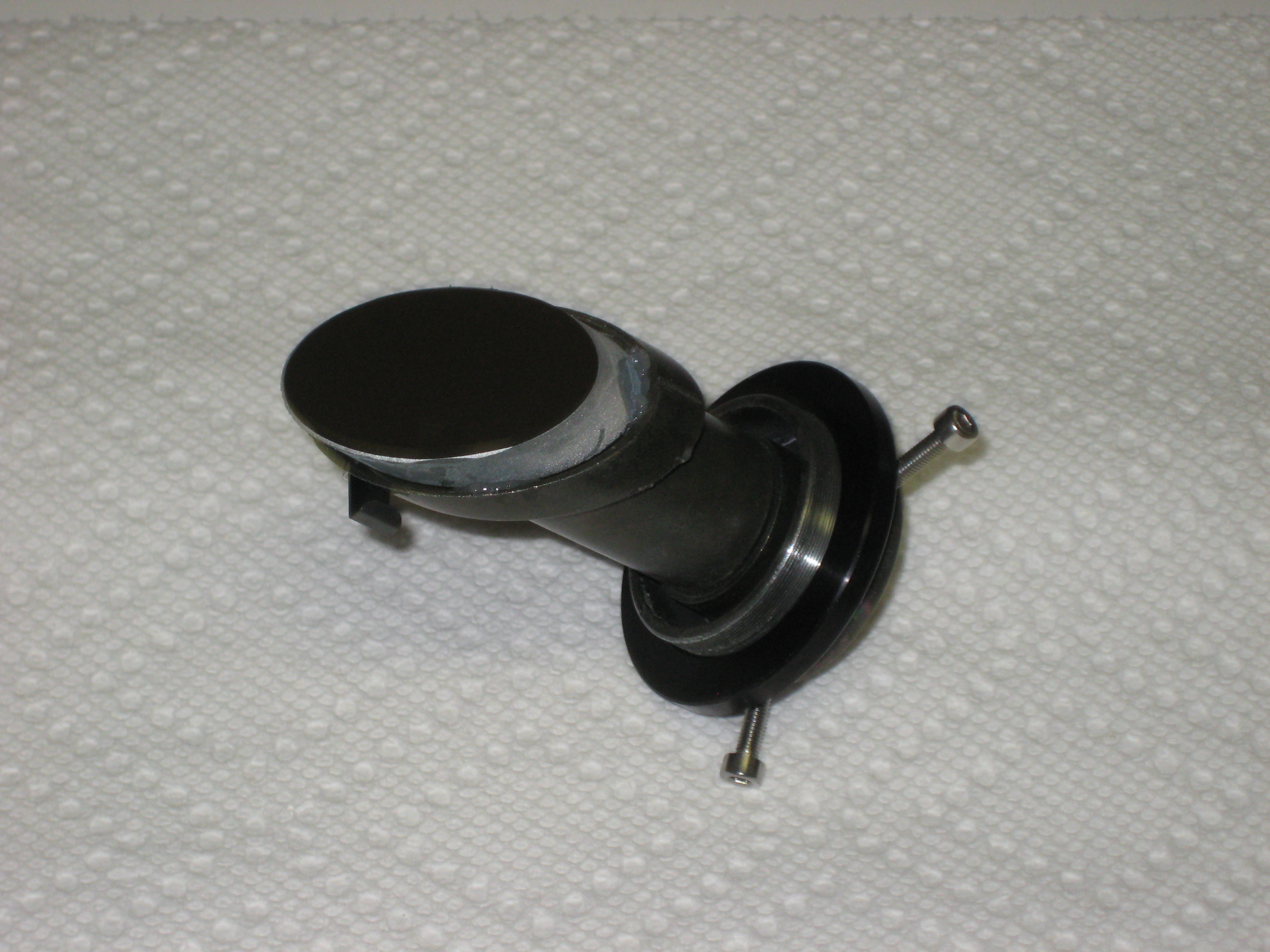
The clip (to left of secondary) is rotated 90°. In this position it scrapes against the inside of the cylinder. I rotated it a further 90° bringing it parallel to the axis of the OTA. (Presumably I should throw it away. It never had a purpose. I covered the screw with a blob of Si glue. It's unlikely to come loose.)
Longitudinal adjustment occurs by looking down the focuser and screwing in the secondary stalk till the secondary mirror is in the middle of the field of view.
I was lucky: This worked the first time (on Max's scope). If I ever wanted to remove the secondary mirror, I just had to cut with a razor blade, parallel to the top of the secondary mount. The bottom and sides of the secondary mirror would have Si glue on them, but this didn't seem to be a major problem. When I repeated the process on the secondary from Milt's scope, The mirror, instead of sitting on its bed of uncured Si glue, sunk into the cavity at the end of the stalk. (Perhaps I was trying to use less glue, so that if I ever wanted to remove the mirror, I would have less glue to cut through.) I had to hurredly fish the mirror out, with the blade of a box cutter. This resulted in removing the mirror with festoons of uncured Si glue hanging off it and on the end of the box cutter blade. On separating the blade from the mirror, I accidentally put a blob of wet Si glue on the mirror. Maybe I should have removed the wet glue, but thinking I would more likely wind up smearing it everywhere, I decided I would try to remove it when it was dry (I now think this was a mistake). I couldn't get it off with cotton balls at least and left the blob there. In the meantime I has a secondary covered in dripping Si glue. I rested it on the box cutter, to let it dry while tried to think of a better solution. When dry, I used the box cutter to cut off the excess Si from the secondary mirror, when I saw clearly that you just can't remove all of it.
I was now committed to the Si glue method. So that the secondary mirror would not sink into the cavity at the end of the secondary stalk again, I did the gluing in two stages. I put 4 blobs of Si glue into the end of the secondary, let them dry and cut them flush with the surface of the end of the secondary stalk.
Here's the four pads (note small blob of Si glue on surface of secondary mirror, closest to viewer)
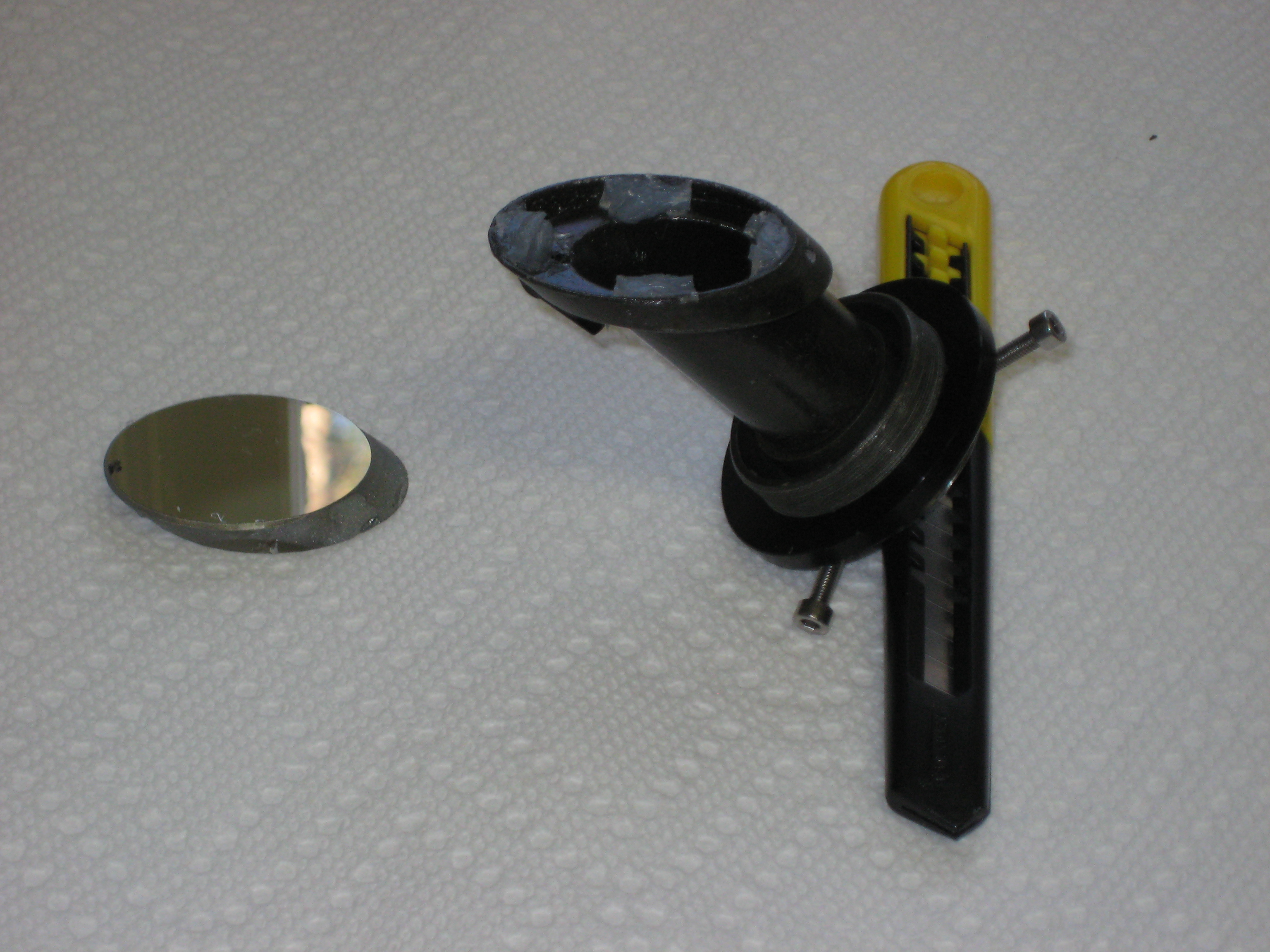
Here's the secondary curing
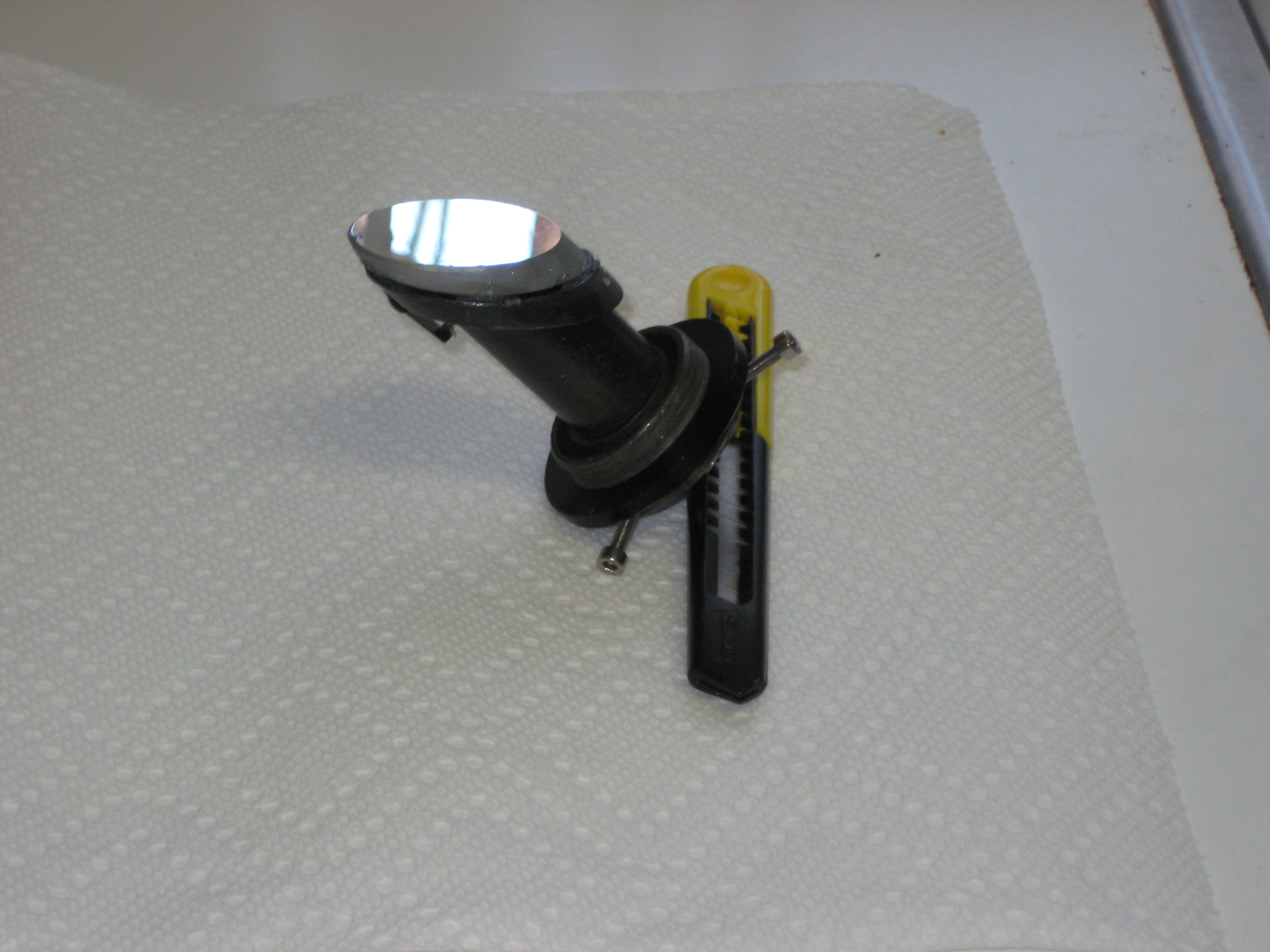
| Note |
|---|---|
| You only need to do this if the aperture in the corrector assembly is wildly out of aligment. The aperture only has to show the whole of the secondary. The aperture is much larger that the secondary and almost any small misalignment can be ignored. The aperature on my scope was adequately aligned and I only removed the corrector cylinder to find out how it worked. | |
The corrector lens assembly is a cylinder with
an aperture facing the focuser
the lenses at the end facing the primary
the other end threaded to fit onto the secondary mount in the plate. The thread is sufficiently tight that the cylinder doesn't really need securing, however there is a small screw at the base securing it. This screw only needs 1.5 turns to disengage it, but I didn't know this when undoing it for the first time.
Note when unscrewing this screw, have the plate vertical, with the screw facing down, so when the screw drops out, it doesn't fall on the glass plate. With my scope, a couple of metal shards came out of the thread. Have your can of greenhouse-gas handy to blow out the exposed threads. Before unscrewing the cylinder, note the orientation of the cylinder (you can only do this approximately) and unscrew the corrector lens assembly. You will have to iteratively position the cylinder on reassembly.
The plate now only has the secondary mount, into which are screwed the secondary stalk (from the outside) and the corrector assembly (from the inside). This secondary mount is held in place by the inner locking ring.
Removal of the inner locking ring reveals a thin inside washer. On Max's scope, the inside washer did not separate from the secondary mount, nor did the secondary mount budge with pushing or attempts to rotate it. To remove the washer, I would have had to stick my fingernail between the glass and the washer. I didn't want to touch the glass. I didn't know whether the washer was hard rubber that, after 30yrs of being compressed in place, would shatter on attempts to remove it. On Milt's scope, the inside washer was loose and the secondary mount rotated freely.
On removal of the secondary mount, the only thing you could do with it is rotate it. However the piece is radially symmetrical and rotating it doesn't get you anywhere. I stopped the disassembly here.
Nomenclature for coordinate system: (the axis of the OTA is assumed to be horizontal, with the focuser up)
- in/out: along the axis of the OTA, towards the primary, away from the primary.
- transverse: when looking down the focuser, movement at right angles to the axis of the OTA.
- up/down/horizontal: when looking through the plate to the primary (i.e. from the front of the scope), up is towards the focuser, down is away from the focuser.
With the corrector cylinder on the plate, reattach the plate (secondary stalk is optional). The axis of the corrector cylinder should be co-linear with the axis of the OTA. Through the cheshire, note the placement of the corrector cylinder in the direction transverse to the axis of the OTA. The profile of the cylinder will make chords with the field of view of the cheshire (you may have to raise the focuser to see the whole width of the cylinder). The chords should be the same length. (This can be seen if you illuminate the inside of the OTA, opposite the focuser, with a flashlight/torch. The cylinder will be black. The only light will be from the two segments bounded by the two chords and the circumference.) In Max's scope, one chord is about 50% longer than the other. Either the focuser is tilted transversally or the secondary assembly isn't in the middle of the plate. This is poor manufacturing, but can be compensated for during collimation.
Next you are going to align aperture under the cheshire. The aperture only needs to allow the secondary to be visible to the focuser (i.e. assuming the secondary is centered under the cheshire, which it isn't on my scope). If too far offset, it will only vignette the image in the eyepiece, but will not affect alignment/collimation. If the aperture is near enough to centered, you're done.
If adjustment is needed, the cylinder may have to be adjusted longitudinally and tranversally. This has to be done iteratively, removing the plate from the scope each time. It should be possible to do all adjustments from the outside. It's bad design when adjustments are done from the inside. However the procedure is simple in principle and should only take a few iterations.
Longitudinal adjustment probably won't be neccessary, but is done by successively rotating the cylinder 360° about its axis, moving it along the thread of the secondary mount. Once the cylinder is in the correct longitudinal position, transverse adjustment is done by small rotational adjustments.
Elevate the OTA so that you can place (i.e. without screws) the plate back into the OTA, without the plate falling out of the OTA. Put the plate, with the corrector lens assembly, back into the scope. Rotate the plate to its final orientions (i.e. so that you could put the screws back in).
With the cheshire, locate the aperture on the corrector cylinder. It should be centered (or close to centered) in the cheshire.
If not, remove the plate, loosen the securing screw at the bottom of the corrector cylinder, rotate the cylinder to fix the offset and reinsert the plate in the OTA.
Rinse, lather, repeat, then put in the screws. If you don't have an acceptable location of the aperture, you're going to have to modify the scope.
I found a flashlight/torch useful to illuminate and identify various parts of the secondary, when I was looking through the cheshire. Identifying the secondary is not easy; the black insides of the OTA don't reflect much light from the flashlight/torch into the aperture.
You do the alignment like a conventional newtonian. Here are some tutorials [26].
Although almost any route you choose will get you there, by the time I'd finished restoring two scopes, I must have done the alignment dozens of times, the alignment changing a bit as the mechanics changed. Here's the way that matches my final setup.
Before inserting the secondary stalk, center the inner annulus and check that the outer ring is free spinning.
The slot will be vertical in the aligned scope.
Note If it's not vertical, you can compensate for this by transversally offsetting the secondary. Then the rays will be coming into the eyepiece a little off axis. This shouldn't cause any major problems. However to make sure this hasn't happened, check that the secondary is transversely centered (as well as the image of the primary in the secondary). Orient the 3 grubscrews so that one is horizontal.
Figure 30. secondary before installation thumbnail
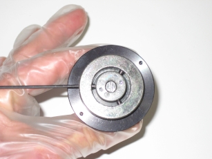 Straight hex key in grub screw is to show that one grub screw is horizontal. Note slot in centre of inner annulus is vertical. When installed, the secondary will have this orientation.
Insert the cheshire. Using only finger pressure (inside gloves), screw in the secondary stalk, till the secondary is centered in/out, and the primary center mark is centered transversally. You will then have to fiddle the locking ring and the secondary stalk, so that the ring/plate/stalk are tight and the primary center mark is centered transverally. You have a bit of play here, in that you can always screw the stalk a little tighter or looser. Check that the slot is vertical and one of the scrub screws is horizontal.
The remaining adjustment on the secondary is to center the image of the primary in the in/out direction. Do this by adjusting the two grubscrews that aren't horizontal.
Check that the image if the primary is still centered transversally in the secondary.
Adjust the tilt of the primary.
Use the your laser collimator to refine your alignment.
Figure 31. alignment seen with barlowed laser thumbnail
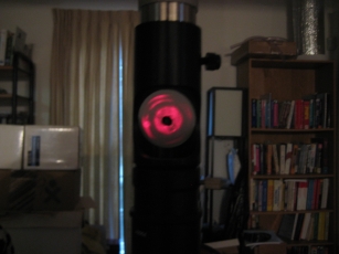 Center red circle is the center of the square ring on the primary. The next region going outwards concentrically, is dark. It's the square ring (round inside, square outside).
Does anyone know what the extra red spot is (about 8:30pm in the photo)? The only thing I can think is that it's the reflection of a tilted concave surface of the corrector lens facing the focuser.
Figure 32. secondary after installation thumbnail
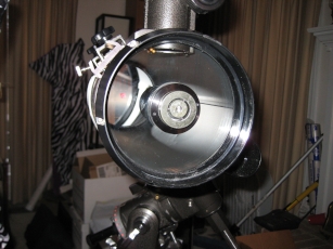 Note primary center marker illuminated by laser. Note vertical slot in center of inner annulus.
Check with the autocollimator.
Replace the outer plastic cap.

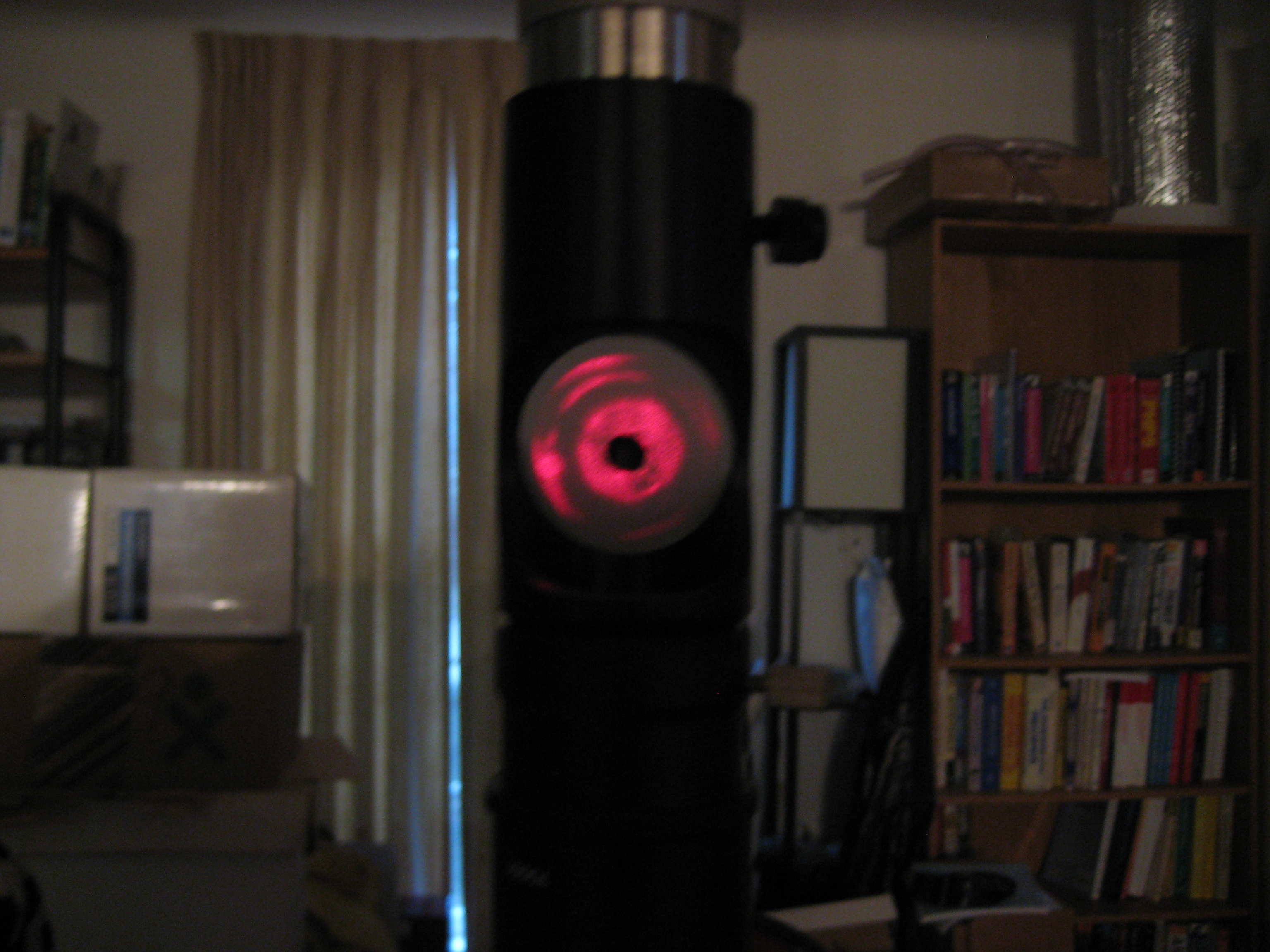

After cleaning the primary on this scope, I decided to clean the primary on my 8" f/6 newt. Stars weren't points anymore and had a fuzzy edge. The scope was 15yrs old and except for observing, was stored in a corner of the living room, the ends sealed with vinyl astronomical sized shower caps. (Smaller scopes were covered with vinyl trashbags.)
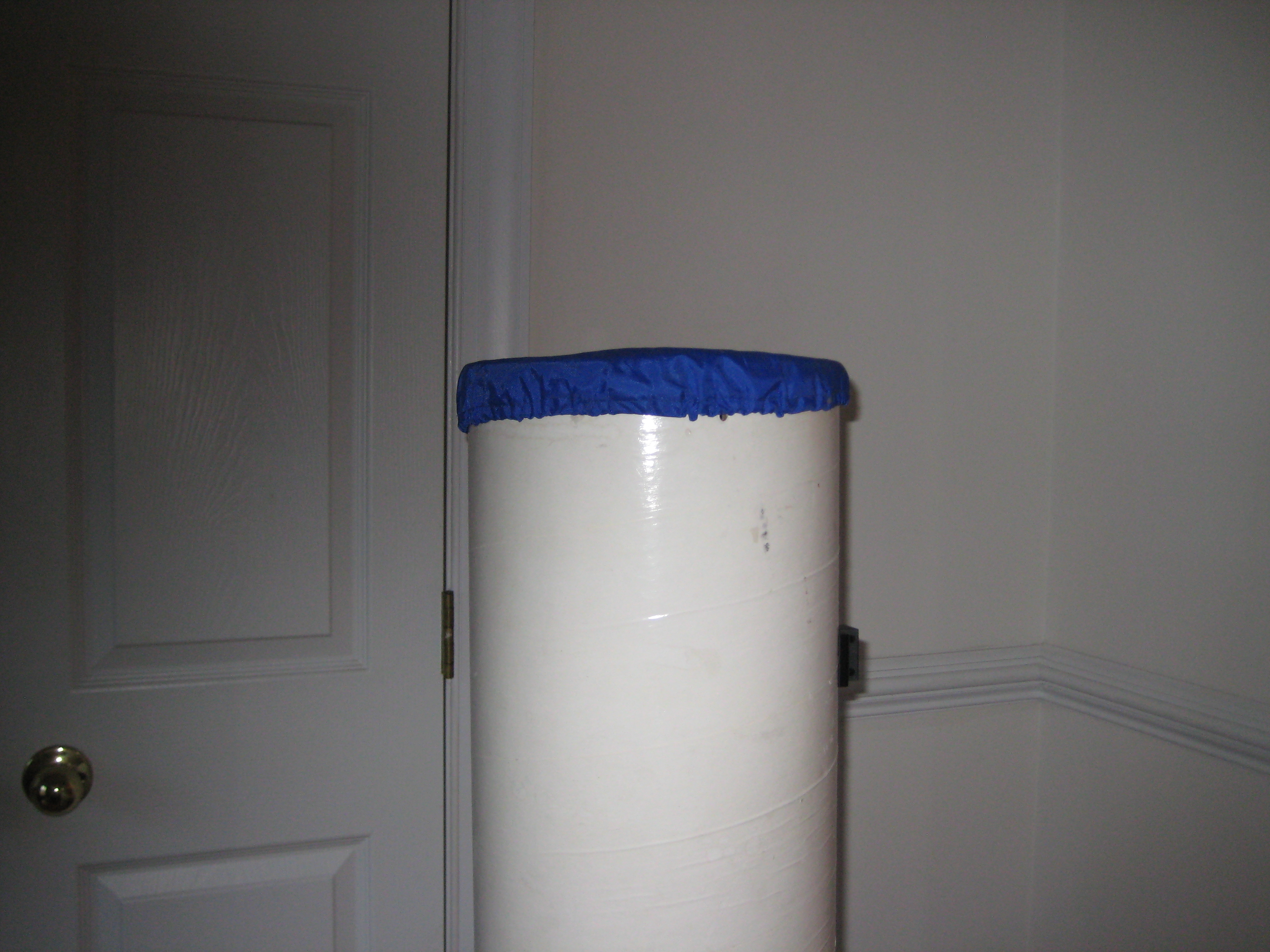
The primary surface was covered in what looked like grey fine grained salt. The standard aqueous cleaning fluids (ROR, Zeiss cleaning fluid, Tiffen) did not wet the surface and several hours of soaking didn't clean the surface or increase the wetting. Soaking the mirror in i-propanol (3 changes * 24hrs) did clean up the surface, allowing the aqueous cleaners to wet the surface. (The aqueous cleaners didn't further improve the surface; maybe the i-propanol was all that was needed.)
I assume then that the primary was coated in organic material rather than dust. The only place that organic material could come from in the sealed OTA, would be the plasticisers [27]in the vinyl of the shower caps. These plasticisers are the same compounds that, over a period of weeks, fog the inside of the windshield of your (relatively new) car and that the EPA says are safe to breathe.
The ideal solution would be a cotton laundry bag or sleeping bag storage sack with a draw string. Laundry bags now-a-days aren't cotton, but polyester (and are mesh). Clearly no sensible economy is going to depend on cotton, a home grown material subject to fluctuations in labour supply and vagarities of weather and insects, when the taxpayers are happy to send the military to invade a foreign oil rich country and set up a friendly puppet government.
Polyester does not have plasticisers. However as part of the manufacturing process, the thread is coated with a mixture of starch and mineral oil to help it move through the machinery. This will come off with one wash in the laundry.
Since laundry bags are mesh, I used long pillowslips (which don't have draw strings, but sometime come with zippers). The ones I have are called "body pillow slips". These are 52" long and fit across a large bed, presumably for couples that can agree to use a single long pillow. Here's my new dust proofing setup. I'll let you know in 15yrs if the mirror stays any cleaner.
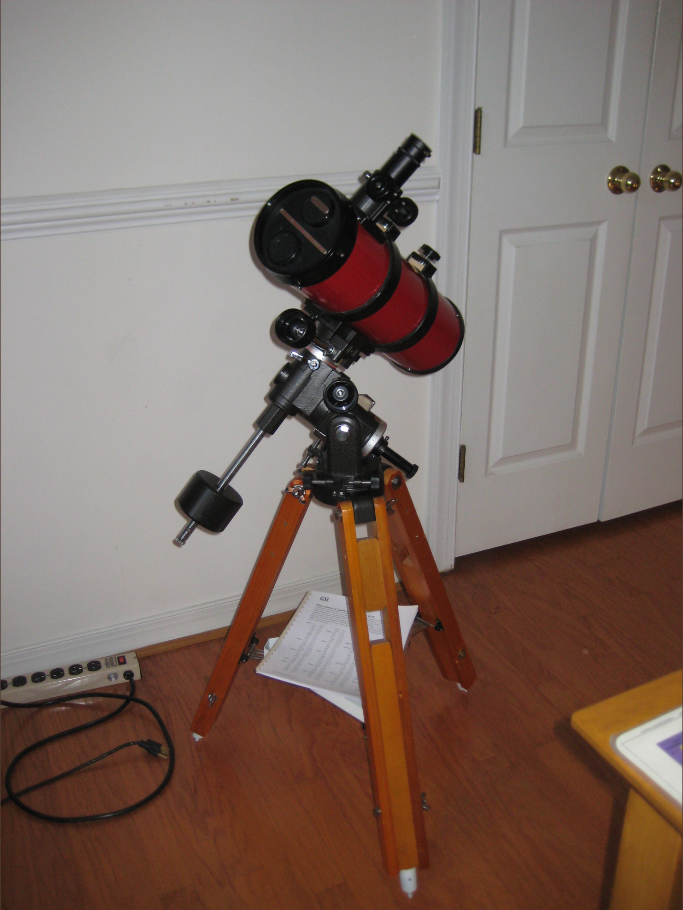
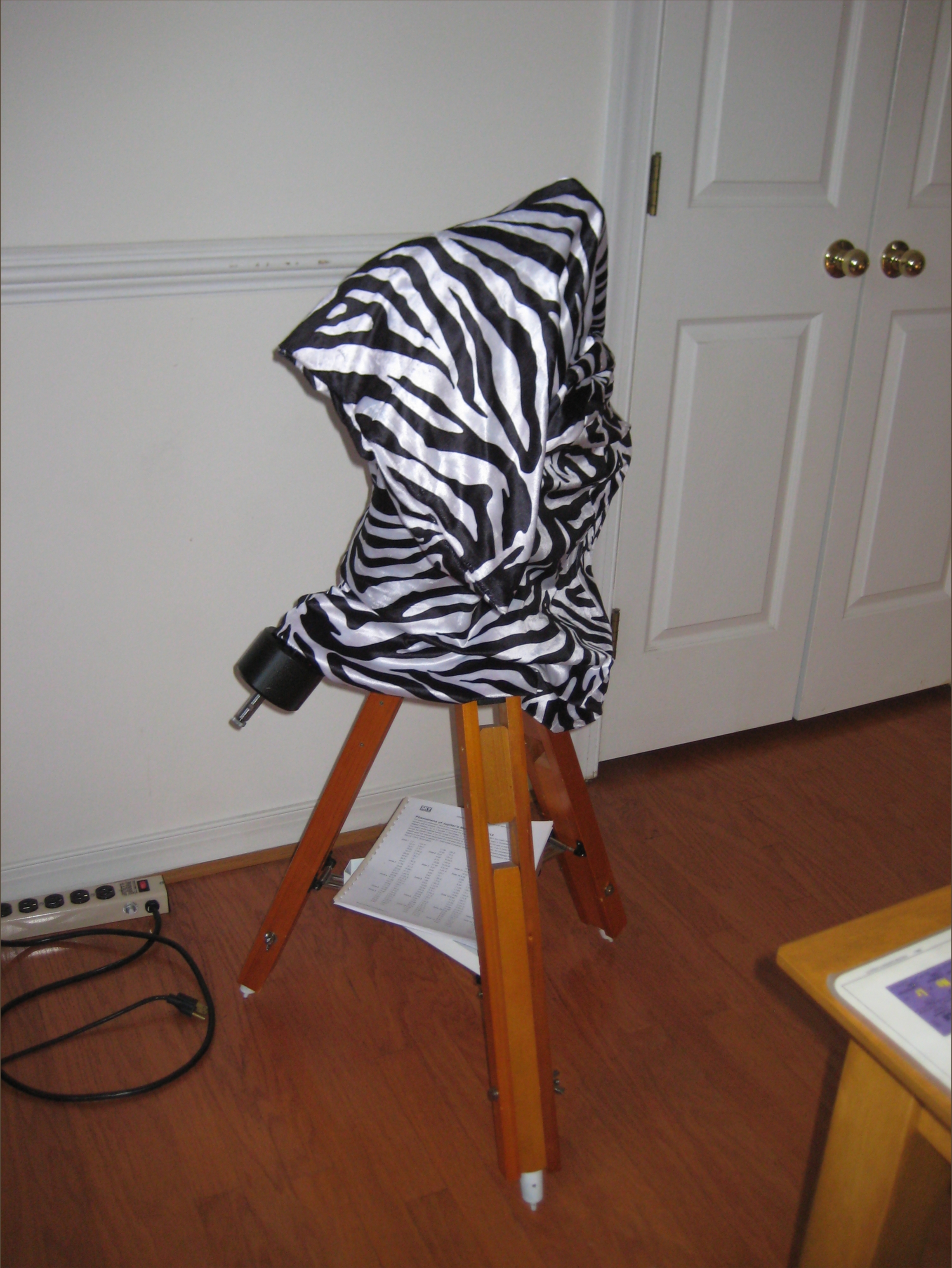
The scope comes with optical accessories
Figure 36. Optical bits thumbnail
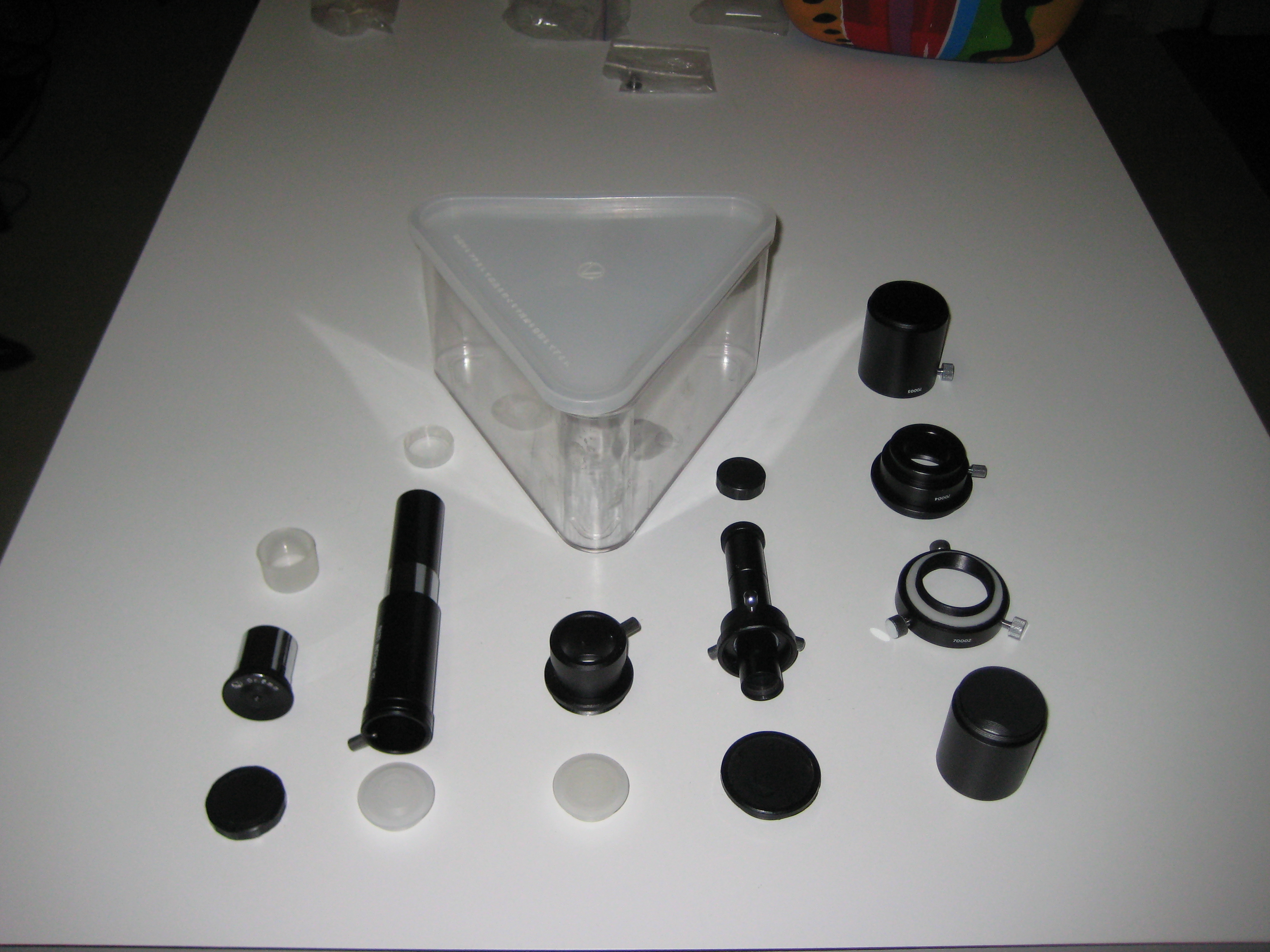 |
From left to right
- 0.965" eyepiece with two end caps (there are 3 eyepieces in the original kit, only one is shown here.)
- 2X barlow with two end caps
- 34.5mm to 0.965" eyepiece adapter for focuser
- Polaris Scope and two end caps (fits inside equatorial head)
- front to back: 70001 34.5mm extender, 70002/70003 (one unit here) and 70004 34.5mm T adapter, 70005 extender.
I first tried using this at a star party after finishing the restoration. A polaris scope sounds a great idea, but as implemented has a few problems
- with the short tripod, you need the neck of a goose to use it.
- the field of view is limited and you have to be already reasonably closely aligned to start.
- the north pole is not Polaris and you have to apply corrections.
- the polaris scope doesn't work in the southern hemisphere. Tasco doesn't acknowledge the southern hemisphere. The tripod is only marked for the northern hemisphere (something that I know irks southern hemispherics, being one myself).
- The lens caps for the eyepiece and the primary end of the polaris scope keep falling on the ground, even when you aren't using the polaris scope. You're going to loose them (as happened to me), presumably each time you remove the cover.
The polaris scope has terrible chromatic abberation. I understand this is normal for polaris scopes; you don't care if Polaris is chromatically abberated. The FoV is about 5°. It has cross hairs, which I can't imagine are much use in the dark. The aperture is 15mm, about double your dark adapted eye. It would.seem not to be much better than a straight-through pipe-sight.
I don't know if the polaris scope gets you a better polar alignment than drifting. I would expect you'd get more accuracy using the 125mm primary of the scope, than the 15mm primary of the polaris scope. I removed the polaris scope and just used the drift method. Presumably you could use the tube, in which the polaris scope fits, as a sight tube.
| Note |
|---|---|
| The gears in the equatorial mount have some backlash. This is to be expected and it didn't give me any problems when drift polar aligning. | |
Summary:
adjust azimuth for object on meridian.
adjust elevation for object on horizon.
The instructions for polar alignment on the internet was complicated and impossible to remember (e.g. do this for a newtonian, do that for a refractor, invert for the southern hemisphere, invert if you're using a star on the western horizon). These instruction require an eyepiece with cross-hairs. I would have to keep printed instructions with the scope. If I arrived at a star party without them, I would be lost. Clearly this is not the way to go.
Here's my polar alignment method. It doesn't require a special eyepiece and only requires minimal notes. It does require a bit of understanding of the celestial sphere.
You need two objects (star, sun, planet...) at the right location. If the two objects are in the mathematically correct position, you can do the polar alignment in two steps. If not, you'll need to iterate to converge on polar alignment. The mathematically correct locations are on the celestial equator where it intersects with
the horizon in the exact east or west position:
You aren't going to be able to observe anything exactly at the horizon. Anything low in the east or west is fine (e.g. the sun, before sunset as you're setting up your gear).
the meridian (the line passing between the poles going through the zenith):
This point is half way between the east and west horizons at an elevation dependant on your co-lattitude.
If you're at 40°N, the co-lattitude is (90-40)=50°. You face the south and the elevation is 50°. If you're at 30° south, you face the north and the elevation is 60°.
In practice anything overhead is fine (unless you're inside the artic/antanarctic circles), e.g. the sun in the middle of the day.
Note: the ecliptic is near enough to the celestial equator for drift alignment.
The equatorial head has two axes of rotation. One is above (vertically) the other. This pair of axes are aligned with the celestial sphere.
RA: This axis points to the pole of the celestial sphere. In the Tasco 8V this holds the polaris scope. It is the lower of the two axes. (This is not the axis with the lead screw and counterweights.)
Dec: This axis is the lead screw and counterweight. It is the upper of the two axes.
The equatorial head has two adjustments to bring the pole into alignment with the RA axis. These two adjustments use the earth based vertical (elevation) and horizontal (azimuth) frames of reference.
elevation: This is adjusted for the latitude.
azimuth: This adjustment is in case the tripod is slightly offset rotationally about the vertical axis.
Unscrew the azimuth adjusting knobs and set the equatorial head in the middle of the adjustment range. You may have to pick up the tripod and rotate it, and this may require relevelling the tripod.
Approximately adjust the equatorial mount
- level the tripod (bubble level). If you don't get this quite right, you can still get a perfectly good polar alignment by drifting. The latitude read-out on the equatorial mount may not be correct, but that doesn't matter.
- set the elevation adjustment using the latitude of your location.
- set the azimuth of the RA axis to point to the pole of the sky (stand back and see if the RA axis points left or right).
The RA axis now points (approximately) towards the poles of the celestial sphere and defines the celestial equator. This will give you the location of the overhead object and the horizon object.
Base information: You need this, either through understanding spherical geometry or by recording it in notes.
- You set the azimuth of the equatorial using the overhead object. (The azimuth is the rotation of the equatorial mount around a line that runs vertically through the mounting.)
- You set the elevation of the equatorial mount using the object near the horizon. (The elevation is marked on the equatorial mount as your latitude, and will change the tilt of the RA axis.)
Figure out which knob controls RA and which controls Dec. You will use the RA knob to simulate the rotation of the sky with time. You will use the Dec knob to bring the object to being tangent to the FoV in the eyepiece.
Functional replacement for the cross hair eyepiece: The cross hairs just provide a reference line to tell if the object drifts. The circular edge of the FoV is just as good a reference line. If you're using a finite sized object (e.g. planet, sun), here's how you do it
- Using the RA and Dec knobs, move the object so the the outside edge of the object just touches the edge of the FoV _and_ moving the RA knob has the object just grazing the inside of the FoV (it doesn't matter which side of the FoV you pick).
- Now you should be able to move the RA knob and have the object come in from outside the FoV and cross into the FoV. Further moving the RA knob, the object will come fully inside the FoV when its outside will just touch the edge of the FoV. Then as you continue to move the RA knob, the object will cross the edge of the FoV again and move out of the FoV. You have just used the RA knob to simulate the rotation of the sky with time. If the scope is polar aligned, then when the sky rotates, you can move the RA knob to compensate for the sky rotation and the object will again graze the inside of the FoV.
If the object is a point (e.g. a star), then you'll need to leave a little gap between the star and the edge of the FoV as the star crosses into and out of the FoV. You will have to estimate if this gap increases or decreases.
Do this for both the overhead and horizon object in turn, till you get no drift. You have to remember a few things (or write them down), so don't try to talk to anyone while doing this.
Initialisation:
- (as above) using the Dec and RA knobs, set the position of the object so that rotating the RA knob has the object grazing the inside of the FoV.
- wait a short time (30-60secs)
- rotate the RA knob again and watch the graze path. If the scope is not polar aligned, the object will now graze the FoV further into or out of the FoV. Remember the direction the object moved.
- Make a small adjustment to the az or el of the mount as appropriate for your object. It doesn't matter which direction, but you'll have to remember which direction you moved.
Drift Loop:
- Re-adjust RA and Dec so that the object just grazes the inside of the FoV
- wait another 30-60secs and check drift.
- Did the drift get worse or better? Either reverse or continue the direction of the adjustment.
- repeat the loop till there's no drift.
For more accuracy, wait longer between drift measurments.
For casual observing, if you level the tripod and have the lattitude set correctly, you only need to adjust the azimuth (eg on the sun at sunset) and you're ready to go.
With a Dobs you plunk it down and go. With an equatorial mount, you spend some time polar aligning it. The first step is to level the base of the equatorial mount, requiring multiple small adjustments of the height of the legs. These adjustments must be easy to perform and must be accurate.
I tackled the tripod after I had the optics working (primary, secondary collimated). I had not expected to have to do anything here. The tripod looked sturdy and I assumed it had been well built. It turns out that even the tripod wasn't fit for use.
When you attempt to tighten the wing nut on the tripod leg height adjustment, the bolt rotates with it. (This is a solved problem outside Tasco.) The size of the wing nut on the top of the leg, at the equatorial mount, and at the bottom, at the height adjustment, are different. Presumably Tasco is trying to maximize the number of parts used.
When removed from the tripod, the wing nut rotates freely on the bolt. The wing nut doesn't rotate freely on its washer when tight in the tripod. Some of the torque tightening the nut, instead is going to rotate the washer on the wooden tripod leg. Inspection of the bottom surface of the wing nut shows it isn't flat; it has a circular ridge around the perimeter left over from the stamping.
The wing nut is small and to get enough torque on it to tighten a tripod leg, your fingers feel the bight. This is not a tripod for little old ladies or retired men.
Miraculously both problems were solved by replacing the wing nut with the largest knob I could find for a M8x1.25 thread [28]. It has a flat base and rotates on the washer, rather than binding to it.
Table 3. Comparison of Tasco 8V original wing nut, ETX-80 tripod tightening knob and Tasco 8V replacement knob
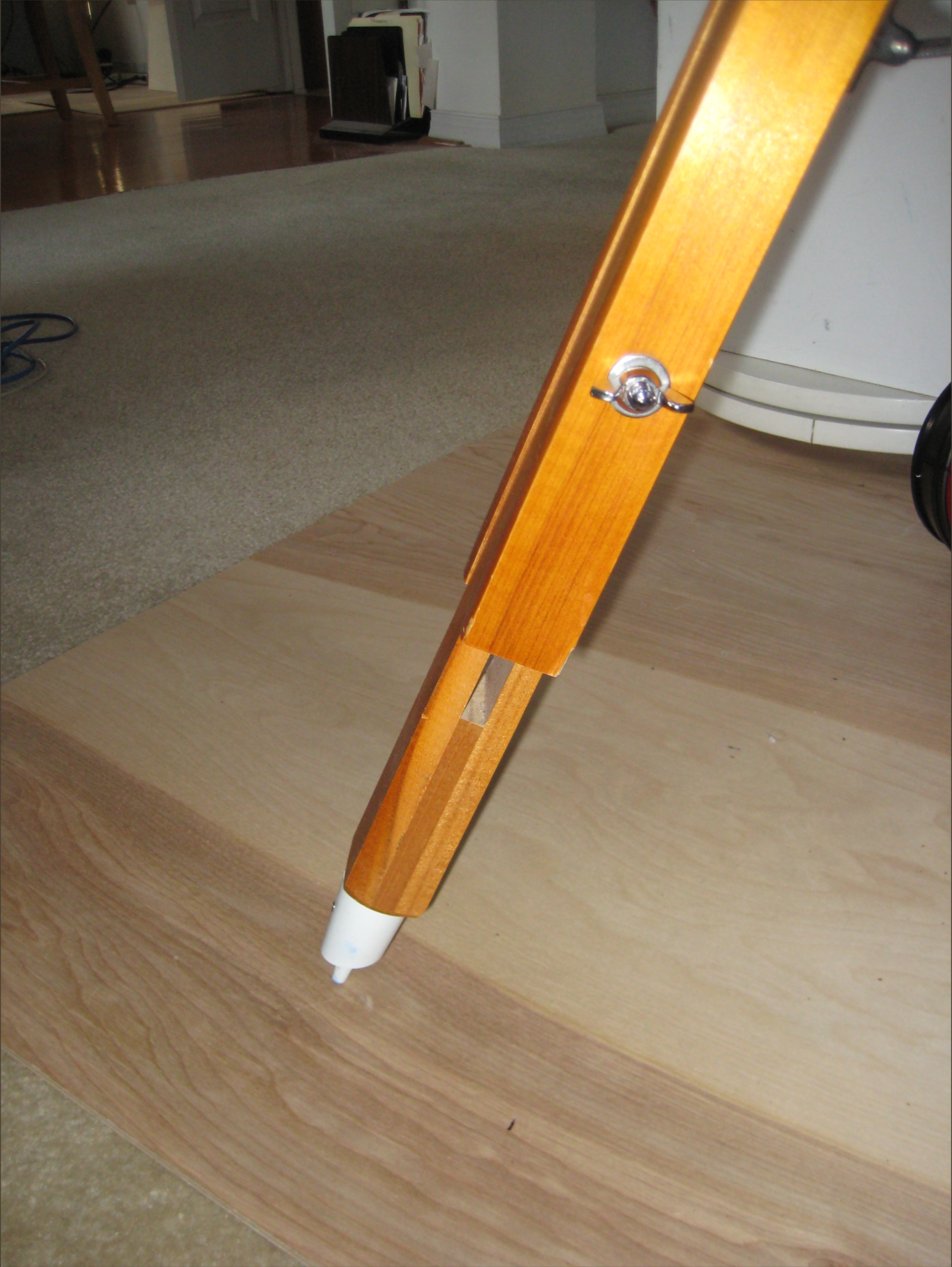
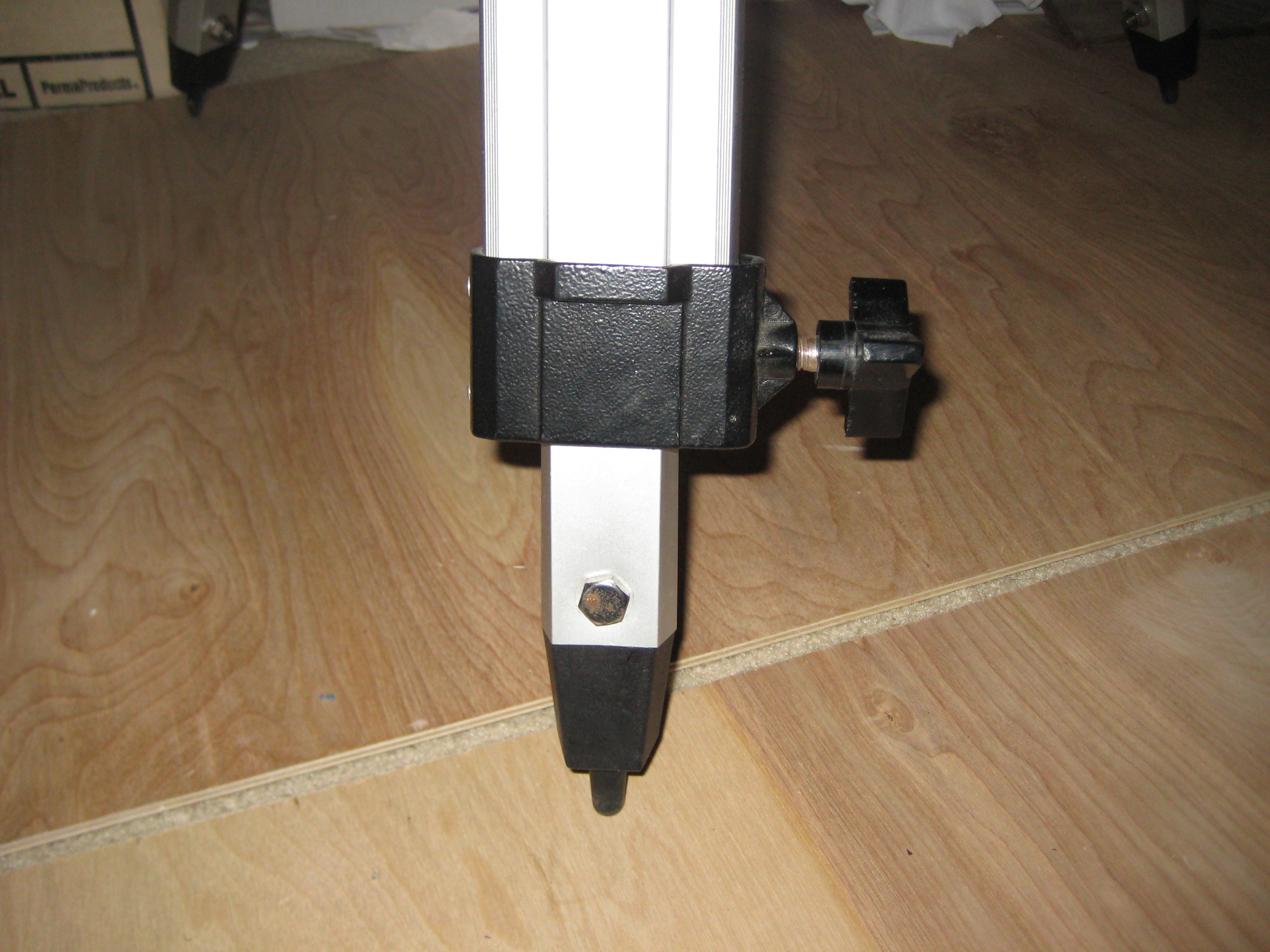
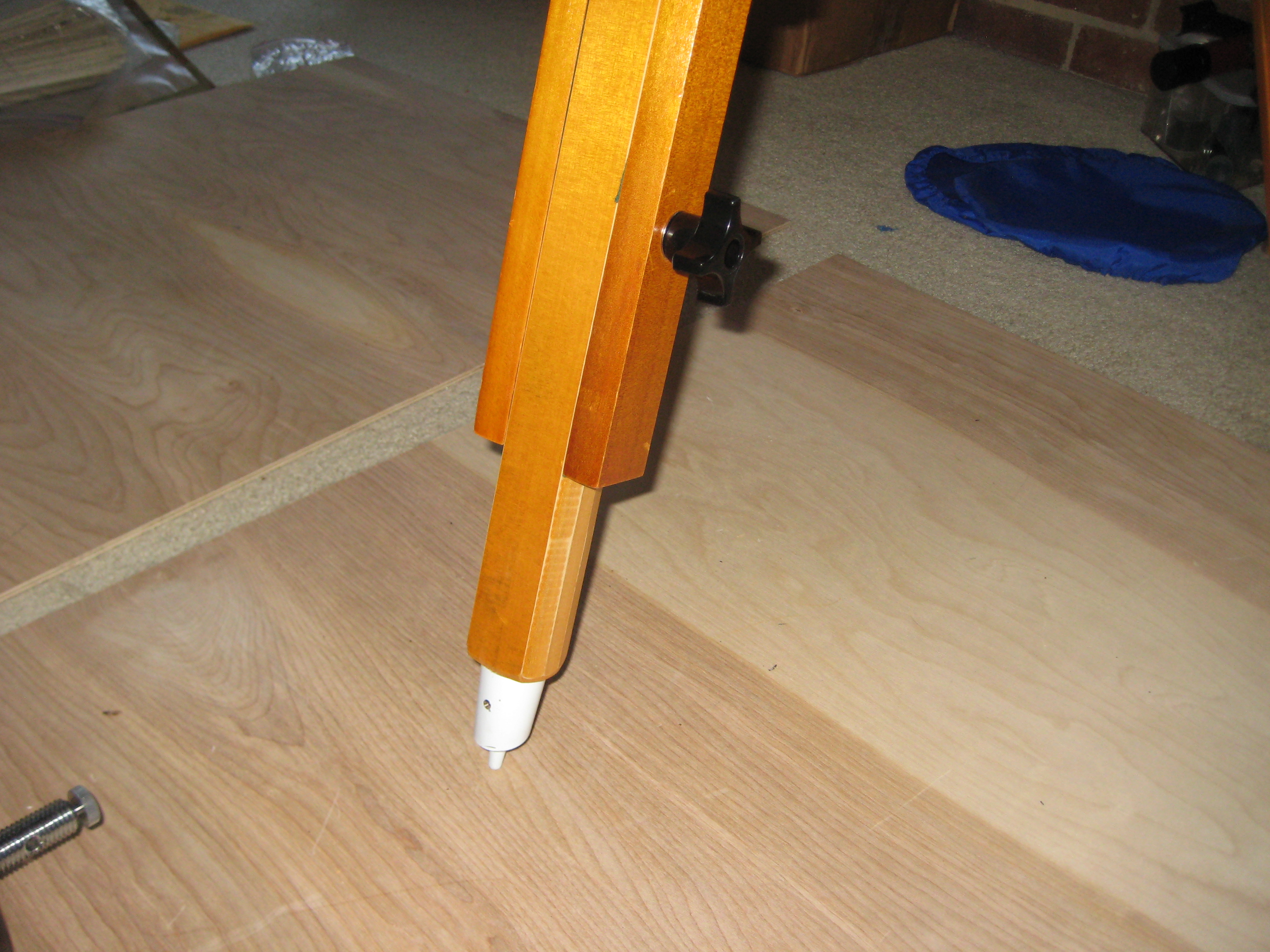
Note plywood protecting carpet.
After you tear up your fingers tightening the wing nut (or later a knob), and you put the tripod leg on the ground, the leg collapses under the weight of the scope.
What happened? Tripod wooden legs usually have flat faces and a pair of bolts to keep the centre element aligned as it moves. When you tighten the bolts, the center element having flat faces, is clamped down. The center element of the Tasco tripod leg however has an octagonal cross section and only one bolt (the bolt that rotates with the wing nut). The orientation of the faces is such that when the leg is in the air (and no weight on the point), the center element gets clamped a little askew (a little like cross threading). When the weight of the scope goes onto the point, the centre element is pushed out of its askew position, into an air gap where it's not clamped and the leg collapses. To get the leg clamped you have to rattle it as you're clamping it, to make sure that, at the final tightening, the center element really is centered. The construction of tripods is a solved problem. Tasco should use one of the known solutions.
Disassembly of a leg shows that the concave inside surface of the outer two leg members is rough cut. Presumably this unfinished surface is left over from the router, which cut out the concave surface. The rough surface doesn't allow the tripod leg members to slide freely. Instead they jam whereever they are when you first start clamping. I could have sandpapered the inner surfaces of the outer tripod leg members. Instead I thought it would be faster to line the rough cut surfaces with felt left over from making the OTA brake blocks. The outside convex surface of the inner leg member is lightly (1 molecule thick) varnished. I assumed it was smooth enough, but on sliding the inside leg member back into the felt lined leg, it caught on the felt as it slid in and out. The partially varnished surface of the inner member was rough to the hand. It hadn't been sandpapered before applying the one molecule thick layer of varnish. I removed the roughness with fine sandpaper (150 mesh, don't let the grit get anywhere near the optics; sand outside on the lawn then blow all the dust off the leg, before bringing it back in the house).
The pictures here show a leg of the tripod with the middle element removed and resting on top of the two outer elements.
| Note |
|---|---|
| This worked OK, but not particularly well. One piece of felt rolled over a little bit and the sticky side caught on the sliding leg element and peeled off. I don't expect the felt solution will work for a long period (e.g. 10yrs) without having to reline the tripod legs all the time. | |
Table 4. Tripod leg before and after lining with green felt

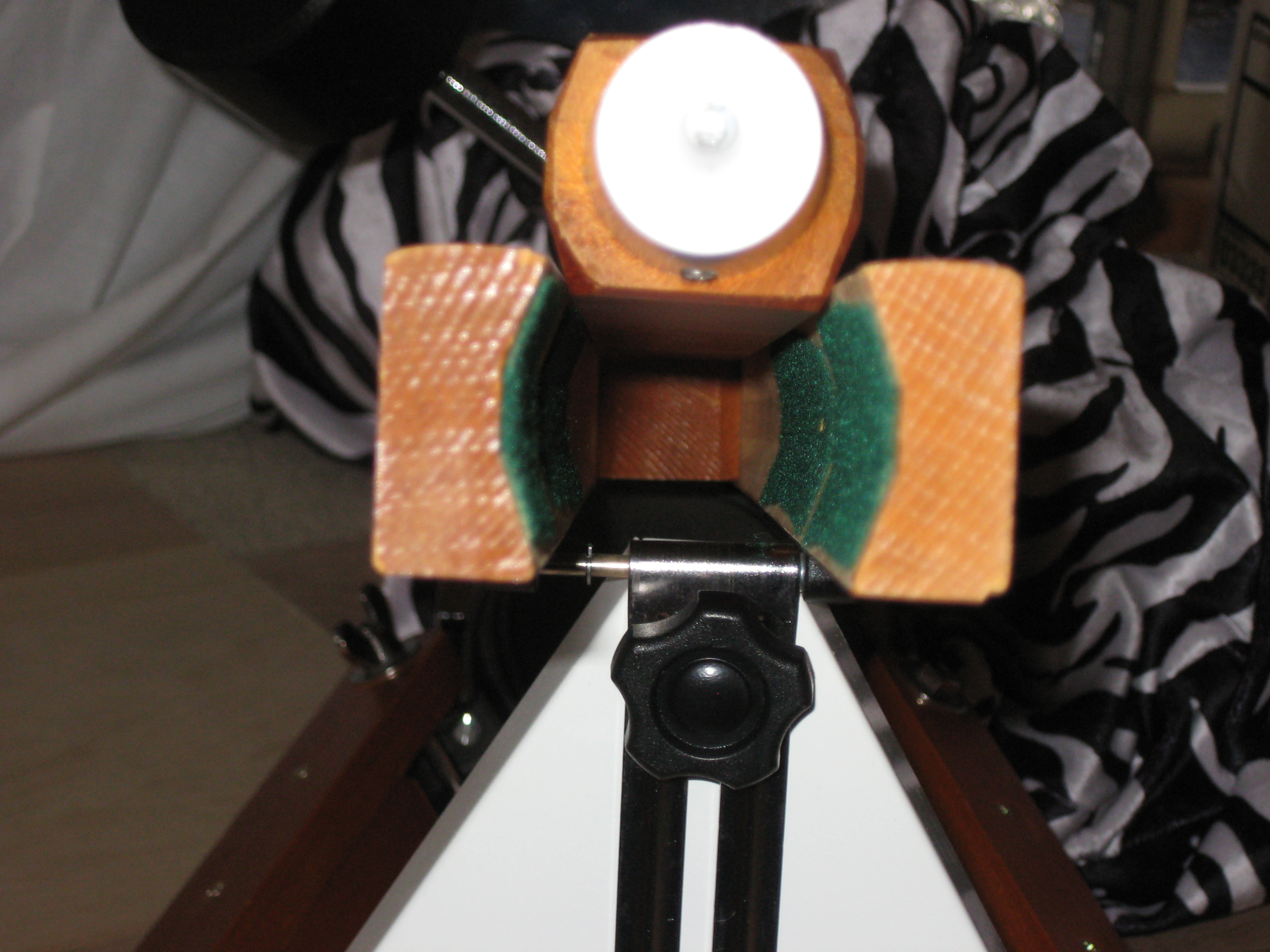
I sanded the inside of the outer elements on the leg where the felt peeled off. Over a couple of night's observing, this worked just as well as the felt lining. Since sanding will last longer than the felt, I removed the felt and sanded all three legs.
The tripod has pointed feet. The scope and tripod weigh 11kg. The points puncture carpet and do nasty things to hardwood floors. The scope and tripod are not house trained. It's hard to imagine anywhere you'd need these points - ice? Do people sledgehammer the legs into the ground? The scope isn't going anywhere in even a stiff breeze even without the points. Even if you cut off the points, the remaining foot is still too small to be house safe and sinks into soil wet after rain making it hard to keep the polar alignment.
I know many tripods have points. Is it because everyone else's tripods have them and people have come to expect them? (Hey, this tripod wouldn't puncture cardboard!) I have one photographic tripod where you can at least retract the points.
The pointed feet are held in by two small Phillips head wood screws.
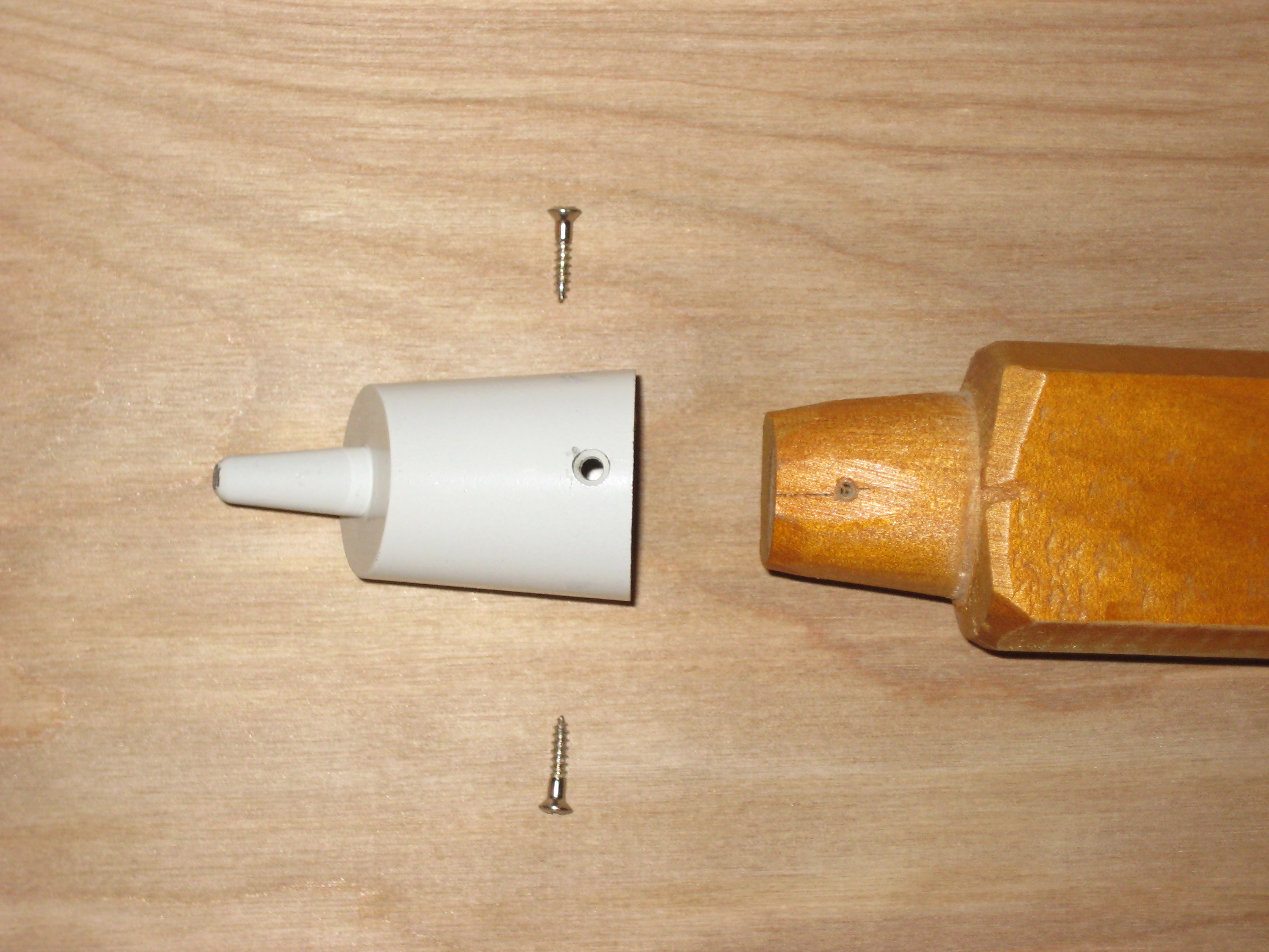
In principle, you can thread the wooden end [29] and attach a glide [30] but the glides are limited to a tilt of 15°. A tripod needs at least 22.5° (30° would be nice). I've run into this problem before, when trying to make feet for tripods for indoor use.
Amateur astronomers operate where the stars are visible. The ground underfoot can be anything (including wet grass in winter that becomes mud after a couple of hours of walking on it). You put down a tarp or mat so that in the morning, you can find what you dropped in the darkness (lens caps...) and to save eyepieces falling in the mud. Tarps and mats are incompatible with pointed tripods. Here's a collection of tripod legs and tarps at the Spring 2013 Staunton River Star Party (one person had the tripod legs sitting on the large plastic lids from pain buckets).
Table 5. Tripod Legs at the Staunton River Star Party
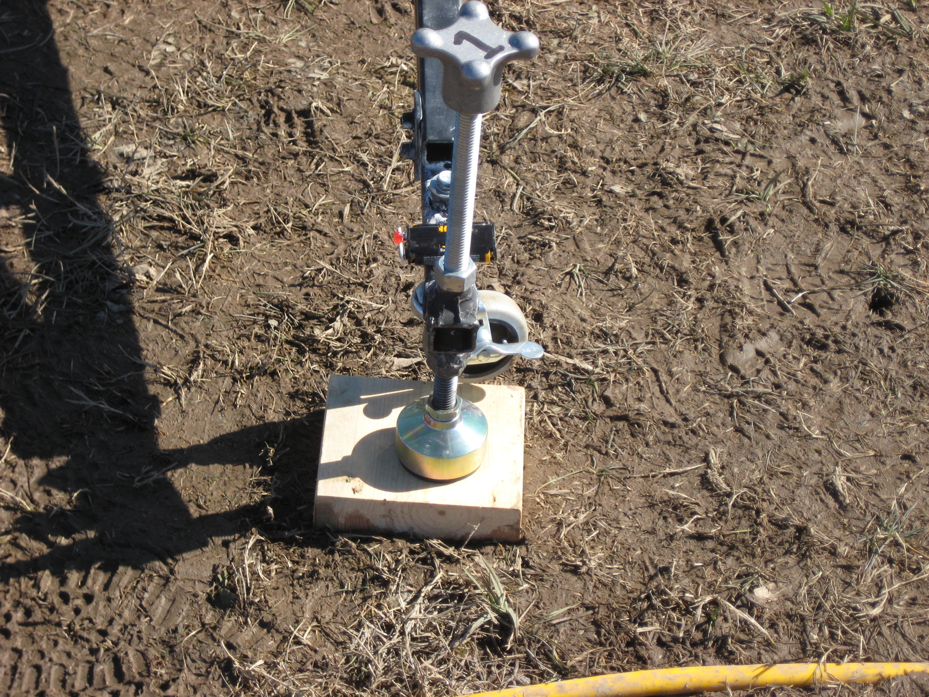

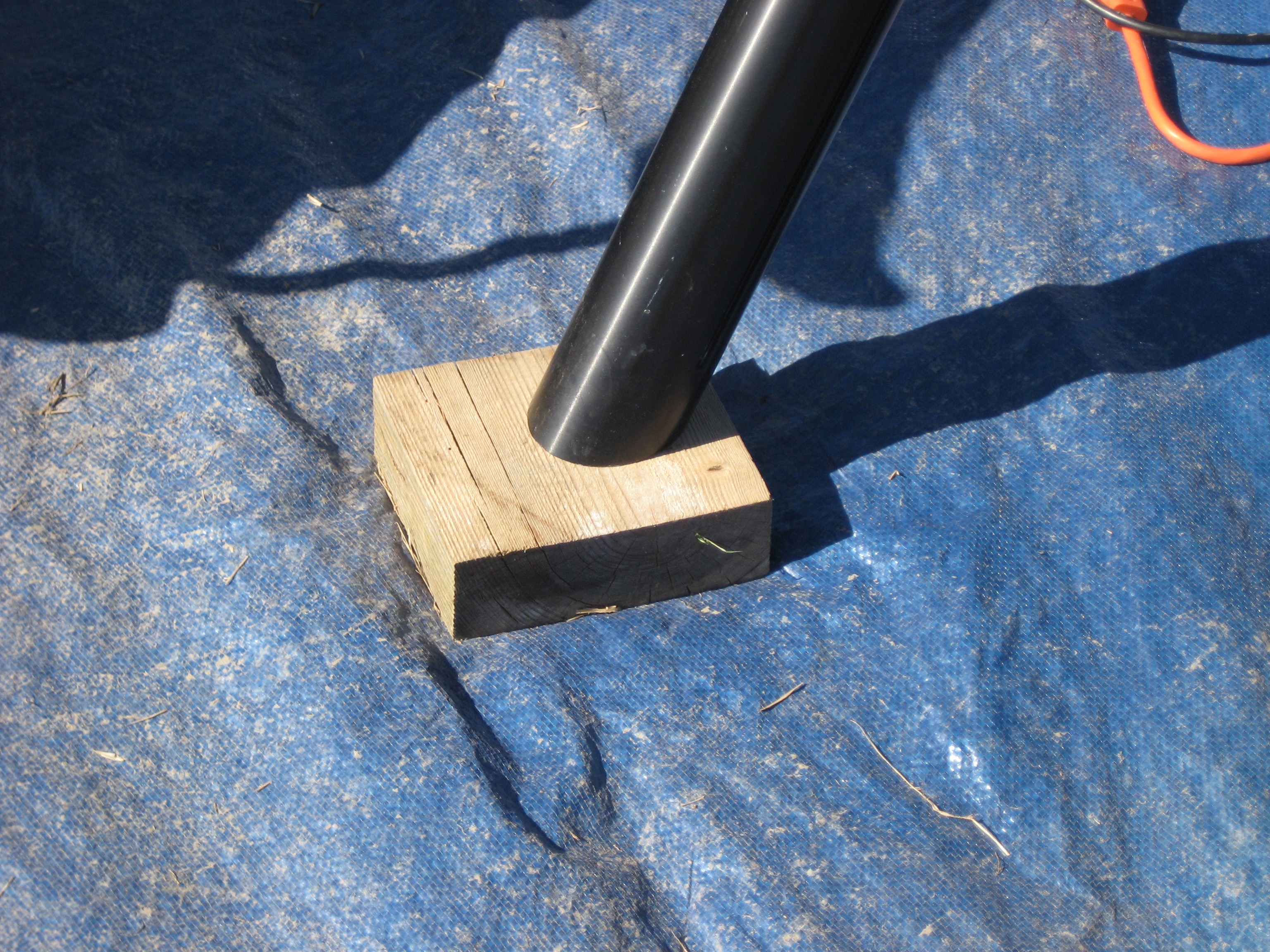
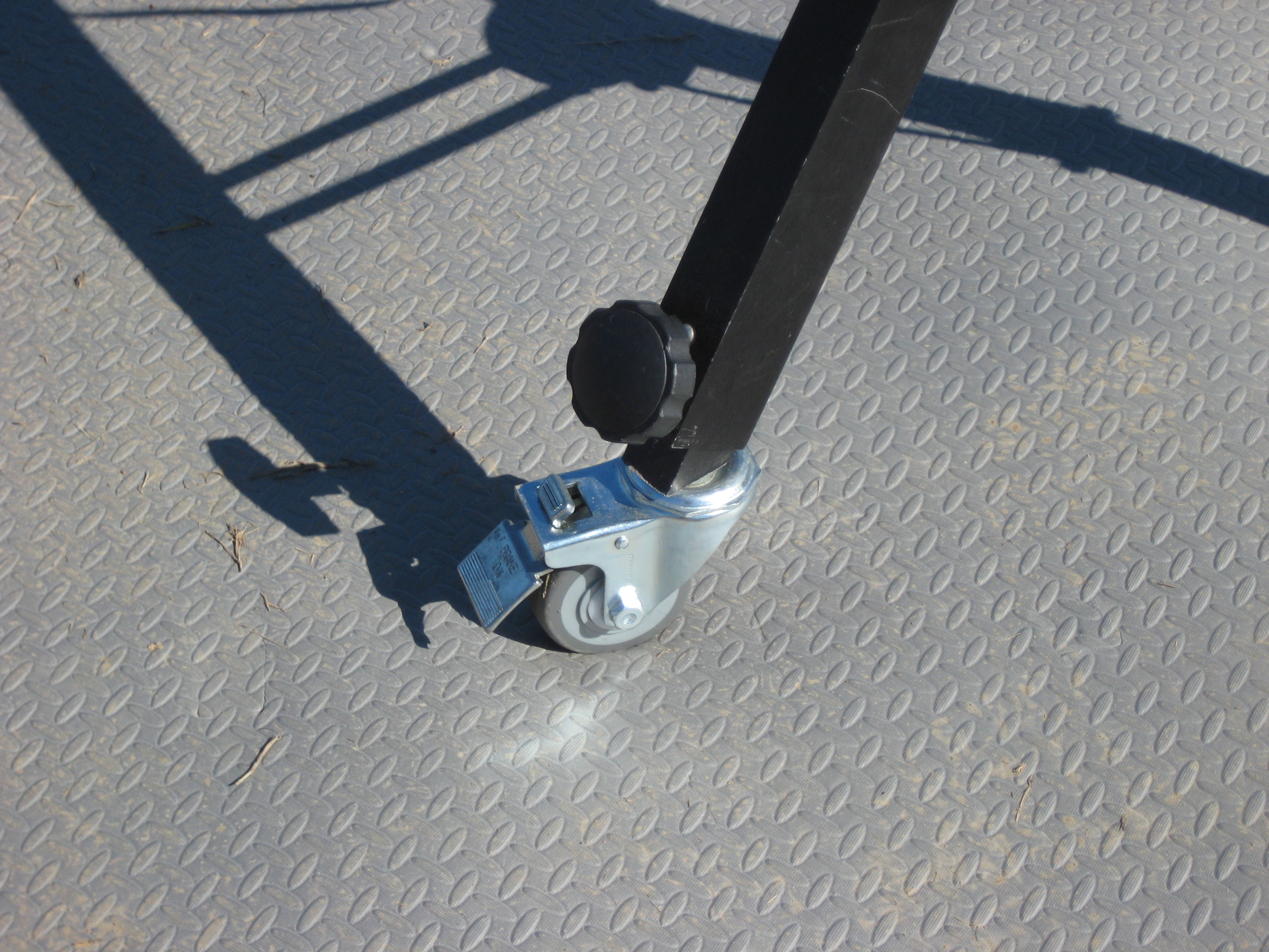
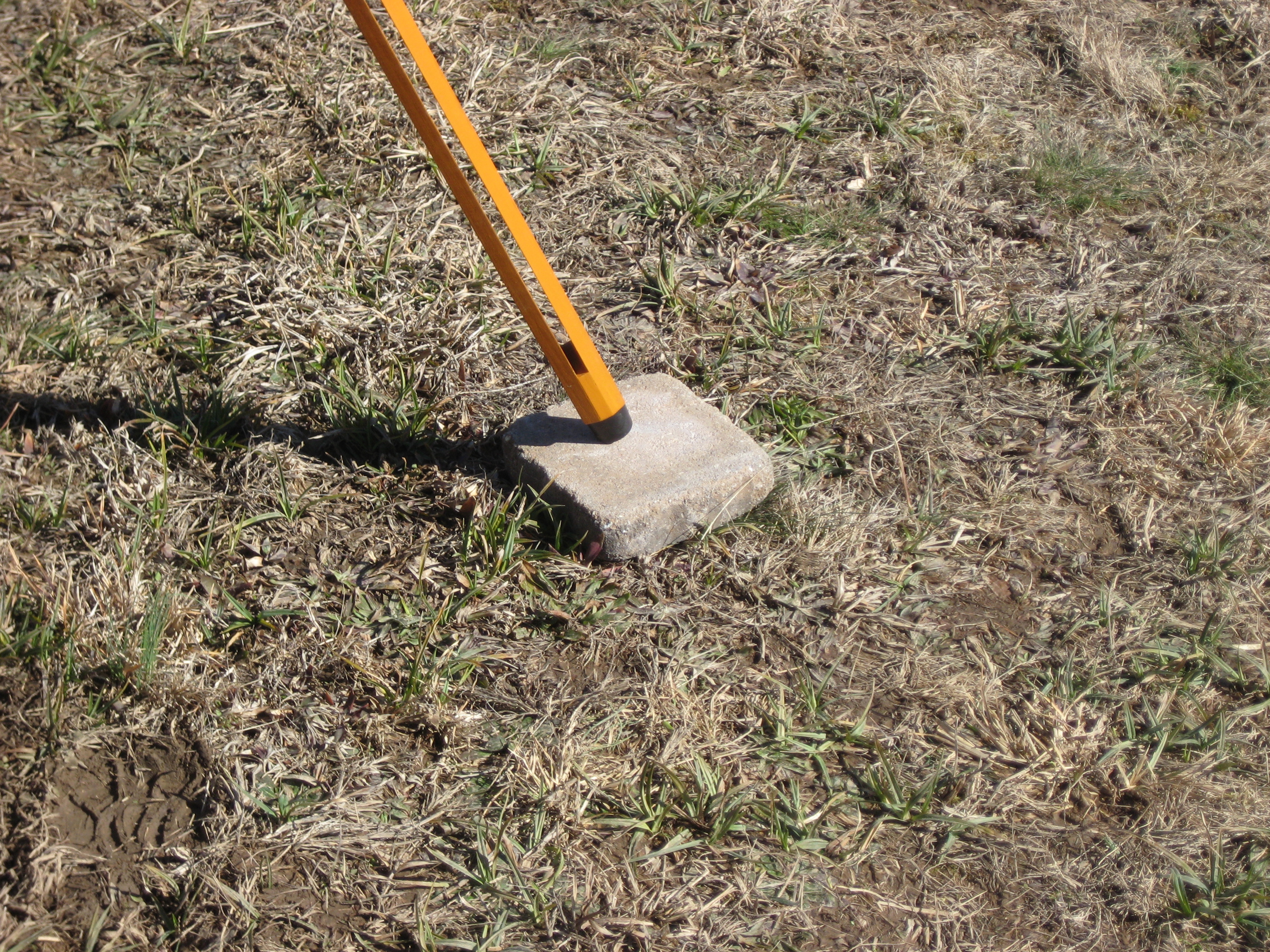
It's clear that few regard their tripod legs as suitable for amateur astronomy. Don't amateur astronomy tripod suppliers go to star parties to see how their products are used?
I took my Tasco 8V to this star party and wasn't prepared to rip up my astroturf carpet. As it turns out both lens caps came off my polaris scope during the night (even though I didn't use the polaris scope; it must have happened when I was taking the cover off). I noticed one was missing before I left the party. The other I didn't notice till I got home. I returned and found it (whew!). All this because Tasco can't supply a tripod suitable for amateur astronomy.
Follow the above examples, I drilled some wooden blocks at an angle to take the points.
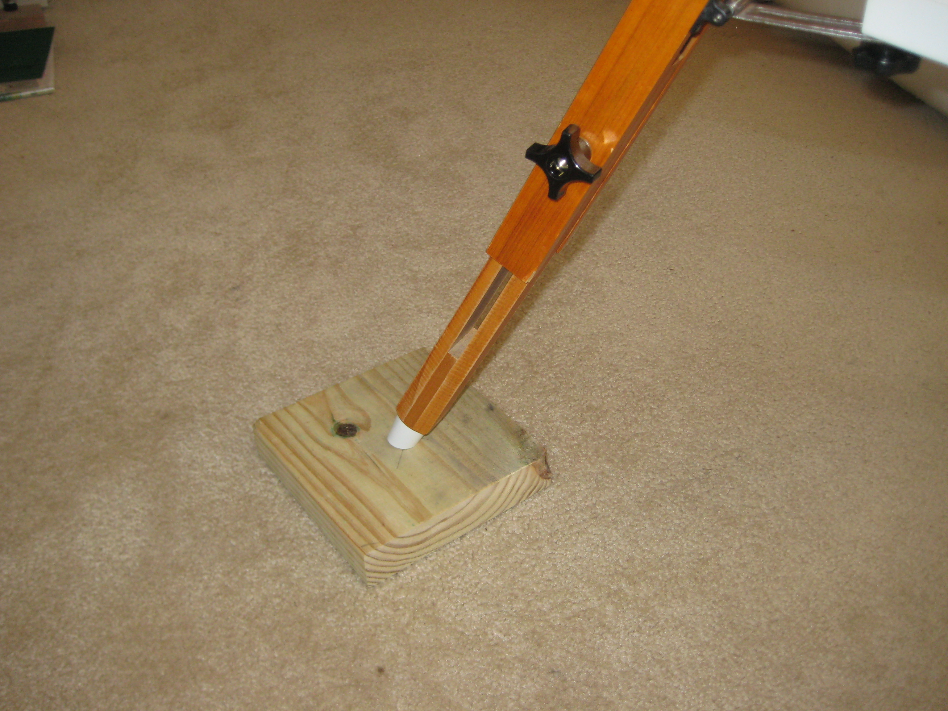
Note carpet. The larger part of the foot (about 1" diam) is sitting on top of the wooden block. Only the point is in the wood. This setup seemed like a good idea, till I forgot to take the wooden blocks with me to an observing session. Here's the cure. The rubber feet are glued on with Si glue II.
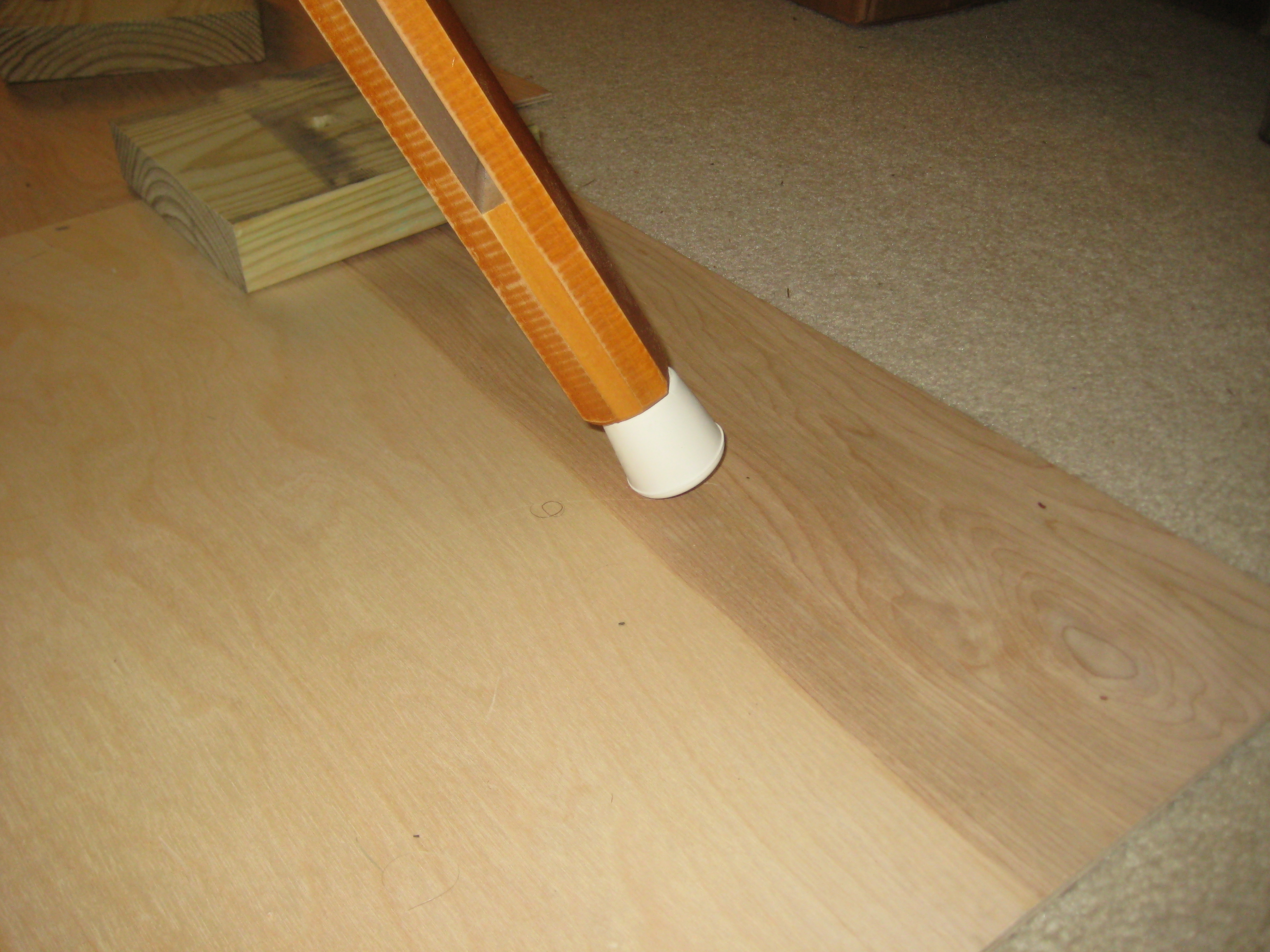
The tripod tray is attached by screws (M5x0.8, 6mm long) on the tray to a flange on the tripod leg. The length of the thread on the screw is short (3 turns), requiring exact alignment of the flange before you can attach the knob. In the field, you'd like to be able to attach the tray without looking underneath to line up the screw exactly. A longer screw thread would have solved this problem. The tray is designed to be attached on a bench at home with the equatorial mount not attached, not in the field with the mount and scope already attached. Tasco seems to like short screws (see also primary cell threads stripped). I changed the screws to 10mm long screws. Unfortunately the knobs aren't threaded the whole way through, so you can't use all of the extra length. I offset some of the extra length with 2 washers under the screw head on the top side of the tray.
I glued the rubber washers between the flanges and the tray, to the tray.
The tripod has only limited extension of the legs (19cm, giving extra height of 19cos(22.5°)=17cm). You have to do your observing from a chair, rather than standing up.
If observing overhead, you need to use the finder scope (which I replaced with a red dot finder) to initially locate your object. To get under the finder, you need to get your head down really low. You can either lie on your back in the mud, kneel with your knee in mud, assume the position of a suckling calf or have a neck that swivels like a goose. (You could have put a tarp on the ground, but the tripod is not compatible with a tarp.) This is painful. This would have been solved if Tasco has used a 2' longer center element for the tripod. When used on sloping ground, you loose the height necessary to compensate for the slope. Clearly no-one who reviewed this scope ever used it.
The tripod height is fine if you're looking at the horizon or testing on an artificial star inside the house.
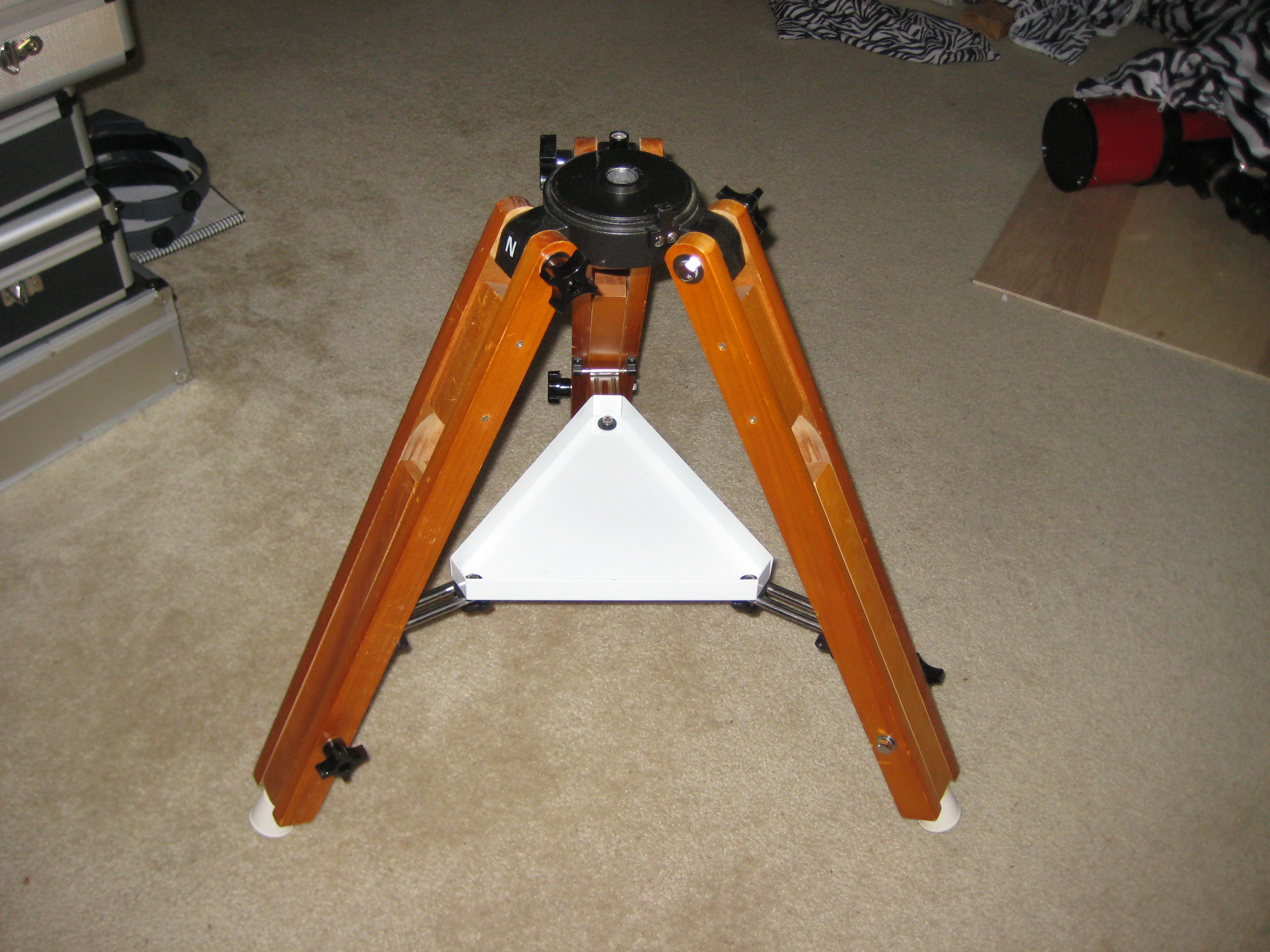
OK the scope works and I'm glad to have it. I was lucky that I didn't loose the primary (see primary not glued down), no thanks to Tasco. Now just about everything works the way it should have when it left the factory (except the tripod is 2' too short). If Tasco had said "here are the optical and mechanical specs" and I found the secondary in the middle of the focuser, all the screws having Phillips heads and were long enough to go into the threads without stripping the few turns that they grabbed onto, screw holes were into metal rather than half way through the walls, then I would have said "fine" and been happy with it. But it seems that Tasco went out of their way, at no cost savings to themselves, to make the purchaser's life as miserable as possible.
On reading my story, Milt remarked
I have read that some of the early Japanese telescopes were in fact put together by small groups of people, literally cottage industries, as opposed to what we think of as a factory.
The question remains is "how did this scope ever make it to market"? Why didn't anyone blew the cover on it? Reading Joe Roberts "Tasco Telescopes: Why they are to be avoided (and how to fix them up)" [31] it seems that Tasco has a history of deceptive advertising and poor equipment. I would expect then that no-one would have reviewed this scope, just because it was a Tasco. This presumably would have been the right thing to do. It's only now with the internet that anyone can publish a review of a telescope, without fears of advertisers withdrawing revenue from your magazine, and you can find out whether the scope is worth buying.
Here's a pair of photos I took about 6hrs apart, while I was looking for the Lunar X. I used a point and shoot camera held above the eyepiece with a Celestron 2" Universal Digital Camera Adapter. The eyepiece is 1.25", AFoV=65°, FL=18mm.
As you can see, the resolution isn't terribly good.
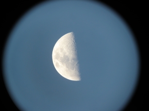
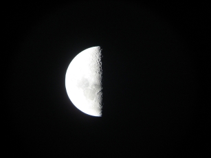
[1] The radius of curvature is 33". This was measured by holding a LED flashlight/torch in front of the scope and locating the image on my hand (which was holding the flashlight/torch). When the LEDs and the image were equidistant from the primary, This located the center of curvature. The focal length is half the radius of curvature. This gives focal ratio = 33/(5*2) = 3.3.
[2] The number f/8 is from the label on the OTA. I couldn't think of a direct test for this. However I confirmed it this way. The 1.25" adapter comes with a translucent cap. At night I focused a street light on the cap (you could see the image on the translucent cap, of the street light, by looking down onto the focuser). The distance from the secondary to the image was about 6" or 16cm. The aperture of the projection of the secondary in the direction of the focuser is 22mm. An f/8 device would produce an image at 17cm above the secondary. This is consistent with the measured distance from the secondary to the image of the street light.
[3] Telescope Optics Evaluation and Design, Harrie Rutten and Martin van Venrooij, 1988, Willman-Bell, PO Box 35025, Richmond, VA, 23235, USA, ISBN 0-943396-18-2, Third Printing.
[4] Astronomical Society of Eastern Missouri (http://www.asemonline.org/Home/telescope-and-equipment-resources/40cm-jones-bird-telescope)
[5] 16" Jones-Bird (https://sites.google.com/a/asemonline.org/grant-martin-s-site/scopes/jones-bird)
[6] "Unusual Telescopes", Peter L. Manly, Cambridge University Press, 1991, p65, ISBN 0-521-38200-9.
[7] Sub-aperture corrector examples: Single-mirror systems (http://www.telescope-optics.net/sub_aperture_corrector.htm)
[8] Yet another home analemma page: the Mack family driveway and windowpane analemma (http://www.austintek.com/astro/analemma/analemma.html)
[9] Cloudy Nights (http://www.cloudynights.com/)
[10] Wikipedia Chlorofluorocarbons (https://en.wikipedia.org/wiki/Chlorofluorocarbon#Phase_out_of_CFCs)
[11] wikipedia tetrafluoroethane (https://en.wikipedia.org/wiki/1,1,1,2-Tetrafluoroethane)
[12] Tasco Vixen 8V (http://www.cloudynights.com/ubbthreads/showflat.php/Cat/1,2,3,4,5,8/Board/classics/Number/3081566/page/162/view/collapsed/sb/5/o/all/fpart/1)
[13] A primer by Company Seven about cleaning telescope, binocular, or camera lenses and mirrors (http://www.company7.com/library/clean.html)
[14] Cleaning Eyepiece and Telescope Optics (http://www.televue.com/engine/TV3b_page.asp?id=103)
[15] I added a layer of cork (from a hardware store) on the inside of the rings. This would produce a tight fit of the OTA in the rings. If I wanted to rotate the OTA I still would be able to with a bit of a push, but it wouldn't move freely again. I glued a strip of cork to the inside of the rings with Si glue II (Si glue I released acetic acid on curing. This pits aluminium. It's OK on glass, wood, iron/steel). To make sure the rings fitted after the cork dried, I pushed the rings back on the OTA wet and let them dry. Pushing the rings on resulted in the cork sleeves coming off the rings, so I had to do some pushing of the cork to get it back under the rings till the glue dried.
Well this was how it was supposed to work. One of the cork rings was too tight and while trying to rotate it, I crumpled the OTA with the palm of my hand. The two rings appear to be slightly different sizes. The cork only covers about 2/3 the circumference of the ring. As the pucker hits the start of the cork, the OTA jams tight. I tried removing some of the cork, leaving gaps here and there. The ring was looser, but now had 4 places where the pucker jammed. I'm going to have to wait till I get back to Australia, when the OTA is in its mounts, to see how this works. In the worst case, I can remove all the cork and have the OTA loose in the mounting rings, and hold the OTA in position with a bungee cord. It won't look pretty but it will work until I figure something better out.
[16] Mars Climate Orbiter (https://en.wikipedia.org/wiki/Mars_Climate_Orbiter)
[17] Wing & Bar Knobs (1/4-20 Thread) (http://www.leevalley.com/us/wood/page.aspx?p=61658&cat=1). I ordered "D" in the diagram, 1-1/8" Wing Knob, Male, 1" Stud, each Item 00M5102. The original Tasco knobs have a 5/8" shaft. This is longer than required for attaching the OTA to the mount and may have been responsible for the original dings. The cut down the 1" shaft to 1/2" with a hacksaw, so there's no chance of the screws dinging the OTA.
[18] Hubble 5-star Artificial Stars (http://www.hubbleoptics.com/artificial-stars.html)
[19] Re: converting 0.965 format to 1.25" format (http://www.cloudynights.com/ubbthreads/showthreaded.php/Cat/0/Number/3487278/page/0/view/collapsed/sb/5/o/all/vc/1)
[20] Jae showing a few of these extenders in use on a refractor (http://www.cloudynights.com/ubbthreads/attachments/3487278-DSC_1229%20%28Medium%29.JPG)
[21] ScopeStuff (www.scopestuff.com) a well done web page, no flash or blinkies, no prompt telling you to upgrade your browser. He's not on facebook. He's just selling stuff.
[22] Reidsupply.com AMF-257, 2mm pins. (measured) min separation of pins 7mm. max separation of pins occurs with jaws open 180° is about 210mm.
[23] Tasco 8V secondary disassembled (http://www.cloudynights.com/ubbthreads/showflat.php/Cat/0/Number/3231597/page/183/view/collapsed/sb/5/o/all/fpart/1) discussion
[24] Tasco 8V secondary assembly (http://www.cloudynights.com/ubbthreads/attachments/3231597-Tasco%208V%20secondary%20assembly.JPG) photo
[26]
- Collimation And The Newtonian Telescope V.4, By Donald E. Pensack With illustrations/pictures courtesy of Jim Fly and Jason Khadder (http://www.cloudynights.com/item.php?item_id=2677)
-
John Reid
- Collimation (http://www.propermotion.com/jwreed/ATM/Collimate/Collimate.htm)
- Using the Cheshire (http://www.propermotion.com/jwreed/ATM/Collimate/Chesire.htm)
- Using the Laser (http://www.propermotion.com/jwreed/ATM/Collimate/Laser.htm)
- A simple guide to collimating a newtonian reflector (http://www.astro-baby.com/collimation/astro%20babys%20collimation%20guide.htm)
- The autocollimator and its reflections (http://w1.411.telia.com/~u41105032/Acoll/Acoll.htm)
- FAQ about collimating a Newtonian Telescope (http://w1.411.telia.com/~u41105032/kolli/kolli.html)
- Rear view barlowed laser collimation By Steve Smallcombe (http://www.smartavtweaks.com/RVBL.html)
[27] Plasticizer (https://en.wikipedia.org/wiki/Plasticizer)
[28] Reid Supply. Knob DK-1181, M8x1.25, black glossy phenolic 4 lobed thru hole brass insert, part 2-284-601 Note: even though it's a metric knob, the dimensions are in inches. This was really confusing, when I was trying to figure out its size. It's about 4.5cm (1.75") across the lobes.
[29] E-Z Lok inserts for soft wood (http://www.catalogds.com/db/service?domain=ezlok&command=browse&category=inserts_for_soft_woods)
[30] Medium Duty Leveler (http://www.furnitureglides.com/medium_levelers.html)
[31] Tasco Telescopes: Why they are to be avoided (and how to fix them up) (http://www.rocketroberts.com/astro/tasco.htm)